


© 2007 • All rights reserved. 7
DLA2RF 2 Room Speaker Selector
2. System Design Overview
There are three typical system applications when installing the DLA2RF:
Standard A/V or Stereo Receiver
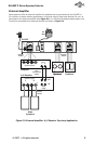
Zone 2 Output of an A/V Receiver
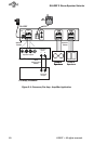
External Amplifi er
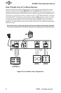
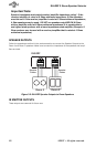
Standard Audio/Video or Stereo Receiver
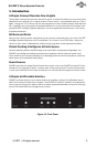
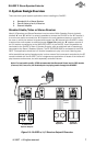
Most A/V Receivers and Stereo Receivers have two sets of Main Speaker Outputs (typically
labelled “A” and “B”. While it is certainly possible to connect the DLA2RF to the “A” outputs, it
is much more useful to connect the “A” outputs to the main speakers (stereo or surround) in
the room in which the receiver is located and connect the “B” outputs to the DLA2RF in order
to expand the audio system to additional areas. Figure 2-1 shows the “B” speaker outputs of
an A/V receiver connected to to the AMPLIFIER INPUT of the DLA2RF. A pair of speakers are
connected to the DLA2RF’s Room 1 Speaker Outputs, while an additional pair of speakers is
connected to the Room 2 Speaker Outputs. The RF RECEIVER BASE is connected to the ATON
PORT. This application allows the A/V receiver’s speakers to play in the main listening area,
while two additional pairs of speakers play in other areas of the home-each controlled by the RF
remote included with the DLA2RF. This is a single-source application: all areas of the house will
play the same audio source, but with separately controlled volume.
Note: For best audio quality, ATON recommends that Surround Sound and/or DSP modes
(Concert, Hall, Jazz, etc.) be disabled prior to playing audio through the DLA2RF.
CLASS 2 WIRING
A/V Reciever
Speaker Outputs
Room 2
Speakers
ATON
PORT
PATENT
PENDING
PWR IN
12VDC / 2.1A
AMPLIFIER
INPUT
1
IR EMITTER
OUTPUTS
Speaker
Cables
PS3
POWER
SUPPLY
Room 1
Speakers
Speaker
Cables
RF
Base
+
-
L
L
R
R
B
A
Figure 2-1: DLA2RF w/ A/V Receiver Output B Overview
1.
2.
3.