


6 ©2007 • All rights reserved.
DLA2RF 2 Room Speaker Selector
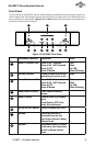
Indicator/Button Function LED
9
Room 2 Select Selects Room 2 for Adjust-
ment
Turns Room 2 OFF if Cur-
rently ON or Selected
Table 1-1: Front Panel Indicators/Buttons
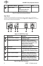
Rear Panel
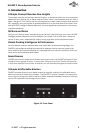
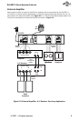
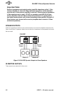
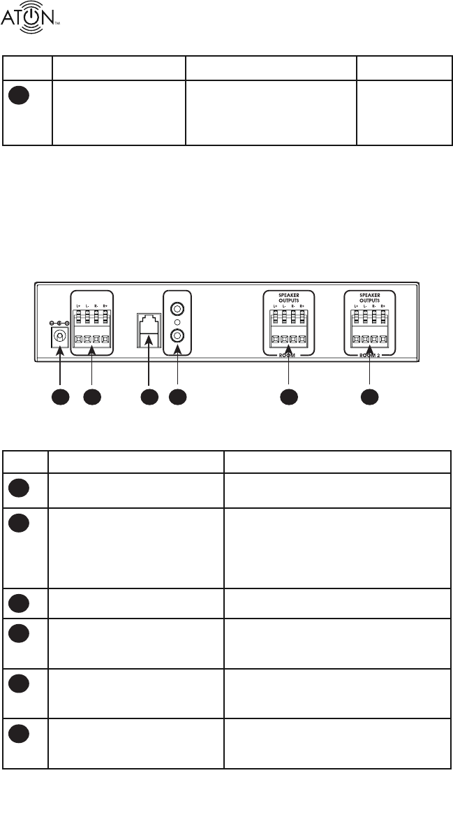
The Rear Panel of the DLA2RF has connections for Power, Amplifi er Input, the RF Receiver
(ATON Port), IR Emitter Outputs and Speaker Outputs. Figure 1-3 and Table 1-2 provide descrip-
tion and location of Rear Panel connections.
CLASS 2 WIRING
ATON
PORT
PATENT
PENDING
PWR IN
12VDC / 2.1A
AMPLIFIER
INPUT
1
IR EMITTER
OUTPUTS
1
2
4
3
5
6
Figure 1-3 : DLA2RF Rear Panel
Conector Function
1
12 VDC Power Connector Connector for +12VDC/ 2.1A Power
Transformer (PS3)
2
Amplifi er/Receiver Input 4-position Fliplock Connector for
16 Gauge, 4 Conductor (16/4 AWG)
Speaker Leads From Amplifi er or A/V
Receiver Speaker Outputs
•125 Watts per Channel Max
3
ATON Port Connects to RF Receiver
4
IR Emitter Outputs 3.5mm Mono Mini Jack Connectors
for Use With ATON IR Emitters (Future
Use)
5
Room 1 Speaker Output 4-position Fliplock Connector for
16 Gauge, 4 Conductor (16/4 AWG)
Speaker Leads to Room 1 Speakers
6
Room 2 Speaker Output 4-position Fliplock Connector for
16 Gauge, 4 Conductor (16/4 AWG)
Speaker Leads to Room 2 Speakers
Table 1-2: Rear Panel Connectors