8 MT2000-0200-01 Rev f (10-2007)
DCN0160
3.2 Shortening of Probe
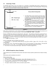
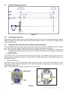
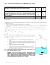
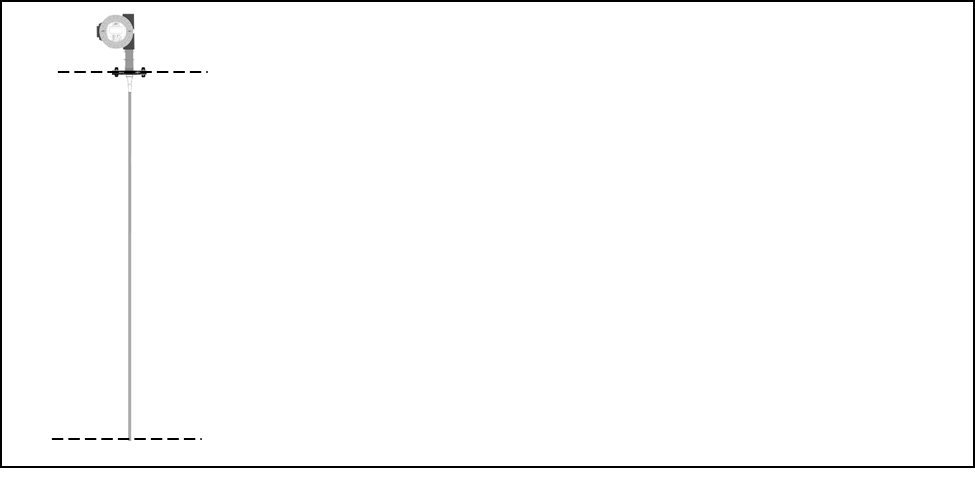
The MT2000 single probe can be cut to length prior to installation. The MT2000 default factory configuration pro-
vides a measurement in engineering units with a zero referenced to the bottom of the sensing probe. The top of the
probe yields a measurement equal to the probe length (Figure 3.2).
20 mAdc
0 in / 0 mm
4 mAdc
Cable Length
Figure 3.2
Factory Default Configuration
1. The default factory setup is with the instrument meas-
uring “level”; This means that the display will indicate
a number equal to the sensor length when the level is
at the top of the vessel. When the vessel is empty it
will indicate zero.
2. If readout in “level measurement units” is not desir-
able, engineering units can be set to percentage (%).
This will provide the readout in percentage of total
level, referenced to the 4 mA and 20 mA points (LRV
and URV).
3. If percentage (%) tank level readout is not desirable,
proceed to Sensor Trim Section (Appendix A).
URV = Probe Length
LRV = 0 in. / 0 mm
Probe Length
0 in. / 0mm
3.3 MT2000 Guided Wave Radar Guidelines
These guidelines are not absolute limits but rather limits that will ensure optimum performance and ease of configu-
ration:
Cable sensor probe is preferred over rigid rod.
Cables in tube or Pipe:
• Use P11 (3/16” DIA) cable.
• In 3” Pipe: 10 Ft. Max cable without spacers, longer cable with spacer every 10 ft.
• In 1.5” or 2” pipe: 7 ft. max cable without spacers, longer cable with spacer every 5 ft.
• Three spacer sizes available for 1.5”, 2”, or 3” sch 160 pipe.
• Two spacer materials available, Teflon and ceramic (above 400°F).
If the probe is shortened, the unit will indicate the distance as if the level was at the place where the probe was cut
off as the lowest value, and read the change in EUN correctly FROM THAT POINT— to the URV.
Example: MT2000 was shipped (and trimmed) with a 10ft. probe. The probe was shortened by removing 3ft. leav-
ing the total length at 7.0 ft. If the transmitter was installed with no further correction, the transmitter display (LL1)
will indicate 3.0 ft. with the level at the end of the probe and 10ft. with the level at the top (a change of 7ft.). To set
the transmitter to transmit 4 – 20 mA over the length of the probe, the following settings would need to be entered in
the CAL menu:
LRV = 3.0 ft and URV = 10.0 ft.
If this is not desirable, one of the following can be done:
1. Change EUN = %. The level will now be shown (LL1) as 0.0% to 100.0%. (Note: LRV = 3.0 ft.; URV = 10.0 ft.
in this example.)
2. Enter L1O = -3.0 ft. The unit will now display 0.0 ft to 7.0 ft for the above 7.0 ft level change. LRV and URV
must be set (LRV = 0.0 ft., URV = 7.0 ft.) accounting for the offset, matching the display (0.0 to 7.0 ft).
3. Re–trim the unit to the actual sensor length – see Sensor Trim Section (Appendix A).


