


2 MT2000-0200-01 Rev f (10-2007)
DCN0160
TABLE OF CONTENTS
1. INTRODUCTION ................................................................................................................ 4
2. OVERVIEW ........................................................................................................................ 5
2.1 Storage Information ......................................................................................................................... 5
2.2 Ambient Temperature ..................................................................................................................... 5
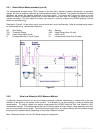
2.3 Description & Principle of Operation ............................................................................................ 5
2.3.1 Direct Reflect Mode (standard) ..........................................................................................
5
2.3.2 Ultra Low Dielectric (ULD) Measure Method
......................................................... 6
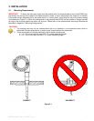
3. INSTALLATION .................................................................................................................. 7
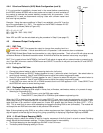
3.1 Mounting Requirements ............................................................................................. 7
3.2 Shortening of Probe .................................................................................................. 8
3.3 MT2000 Guided Wave Radar Guidelines ............................................................................ 8
3.4 Wiring
...................................................................................................................... 9
3.5 ATEX Approval Information ........................................................................................ 9
4. COMMISSIONING .............................................................................................................. 9
4.1 Quickstart Procedure ................................................................................................. 9
4.2 Verify Proper Power-Up ........................................................................................... 10
4.3 Setting the 4mA and 20mA Points Using the Pushbutton Menu ................................... 10
4.3.1 LCD Menu Operation ..................................................................................... 11
4.4 Detailed Configuration Parameters ........................................................................... 12
4.4.1 Direct Mode Blanking Parameter (BLK) .............................................................. 12
4.4.2 Threshold Level Parameter (THV) and Gain Setting (GS) ...................................... 12
4.4.3 Advanced Parameter Settings ......................................................................... 13
4.4.4 Ultra Low Dielectric (ULD) Mode Configuration .................................................... 15
4.5 Advanced Output Configuration ................................................................................ 16
4.5.1 DAC Trim .................................................................................................... 16
4.5.2 Setting the DAC Trim ..................................................................................... 16
4.5.3 Displayed Engineering Units (EUN)................................................................... 16
4.5.4 4 - 20 mA Output Damping (DMP) .................................................................... 16
4.5.5 Bench Calibration of the 4mA & 20mA Points ...................................................... 17
4.5.6 4mA & 20mA Calibration Using Actual Level Input ............................................... 17
4.5.7 Reversing the Output Action Using Actual Level Input ........................................... 18
4.5.8 Jumper Switch Settings .................................................................................. 18
5. TROUBLESHOOTING INFORMATION ........................................................................... 19
5.1 Valid Current Loop Outputs ...................................................................................... 19
5.2 Possible Symptoms ................................................................................................. 19
5.3 Electronics Module Replacement .............................................................................. 20
6. HONEYWELL DE OUTPUT OPTION ............................................................................... 20
6.1 Interoperability and Conformance Class .................................................................... 20
6.2 Operating Modes..................................................................................................... 21
7. HART PROTOCOL INTERFACE OPTION ....................................................................... 21
7.1 268 ROSEMOUNT Communicator ............................................................................ 21
7.2 HART AMS ............................................................................................................. 21
7.2.1 Compatibility ................................................................................................ 21
7.2.2 Resource Files ............................................................................................. 21
8. GLOSSARY OF TERMS .................................................................................................. 22