


20 MT2000-0200-01 Rev f (10-2007)
DCN0160
5.2 Possible Symptoms (cont’d)
SYMPTOM ACTION
Raw Counts are 0 and Output is in
alarm
Raise the Threshold
Check probe for presence
Decrease blanking
No Display
Check cables
Check for proper supply voltage
Check for proper wiring
Replace electronics module
21 mA output
Unit is in ALRM – check THV, GS (section 4.4.2); check BLK
(section 2.3.3.3)
OUTPUT steady even when level
moves
Check cable for obstructions, buildup, and trash or nearby metal
objects.
Unit worked satisfactorily until new
IS barrier installed in circuit
Ensure that barrier meets requirements of pg 31 (APPENDIX H) and
that sufficient voltage / power is available for device.
Unit reads incorrectly at the top or
very end of cable / probe
This non-linearity is common at the extreme ends of the probe and can
be minimized or eliminated by using the Linearization table.
After a power loss the unit goes to
4 ma before returning to normal
reading
Normal part of start up cycle
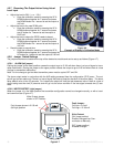
5.3 Electronics Module Replacement
A defective electronics module can be replaced as follows:
1. Before installing a new module record the KO and KG numbers off the new module for future reference. The
numbers are marked on the side of the module in the following format: 1-KO-KG, 2-KO-KG for ranges 1 or 2
respectively.
2. Remove the existing module by unscrewing the 2 flat screws holding the module in the housing.
3. Note the orientation of the module and unplug from the housing base.
4. Carefully unplug the coax cable connector from side of the module.
5. Plug the coax cable into the new module.
6. Plug module onto the housing base.
7. Secure the module to the housing by screwing the 2 flat screws.
8. Power the unit and, using the LCD display, go to the CFG menu to KO and KG and enter the numbers written
down from the side of the new module for RNG1 or
RNG2. (RNG 1 is for probes < 100 ft. / 30.5m.)
The MT2000 is now ready for use without further calibration.
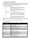
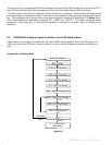
6. HONEYWELL DE OUTPUT OPTION
6.1 Interoperability and Conformance Class
The DE option uses the Honeywell proprietary Digitally Enhanced Protocol for Smart Transmitters. The confor-
mance class is as follows:
The DCS configuration should be set for Class 0, 4 byte Mode.
Class 0: Continuous broadcast, in burst mode, of the following parameters:
PV1: Primary Variable; Level #1 in %
PV Status: OK, Critical or Bad PV