


12 MT2000-0200-01 Rev f (10-2007)
DCN0160
4.4 Detailed Configuration Parameters
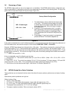
4.4.1 Direct Mode Blanking Menu
Note: This section only applies to direct mode measurement.
The blanking parameter (BLK) is used to ignore an extended nozzle that would otherwise cause a reflected signal at
the top of the probe and result in a high level reading even when no product is in the vessel.
For probe configuration 1,2,5,6 or 7 (Appendix G) use the factory default BLK.
BLK can be changed by accessing SET followed by the CFG menu (refer to menu chart). If the MT2000 is installed
in an extended nozzle or other configuration where the top of the tank is further than 1 inch from the probe coupler
set BLK as follows:
For probe length < 100 ft. (30.5 m) add 4 to the BLK value for every 1 in (2.5 cm) of tank nozzle
For probe length ≥ 100 ft. (30.5 m) add 2 to the BLK value for every 1 in (2.5 cm) of tank nozzle.
Example: RS=1: Nozzle length = 10” BLK=200 + 4(10) = 240
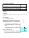
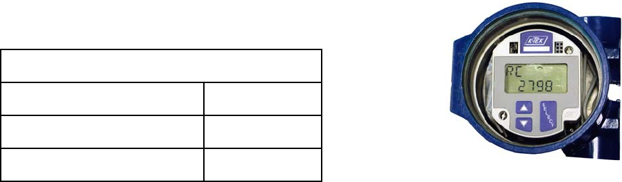
To verify settings are correct, proceed to CFG menu. Scroll down to RC (Raw Count) value display. RC (Raw
Count) will decrease as levels rises and increase as level lowers. Caution: if RC value exceeds 4 digits, then the first
digit is shown on the top line of the display.
If RC stays at a fixed low value around 2000 while the level changes the BLK is set too low and needs to be ad-
justed. Raise the level and stop when RC stops decreasing or top of the vessel is reached, whichever comes first. If
RC stops decreasing before the top level is reached reduce the BLK.
To determine the actual level using Raw Counts use the following formula:
(RC – 2100) / 38 = Distance in inches
(Distance x 38) + 2100 = Expected Raw Counts (RC)
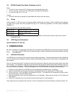
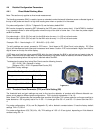
Typical BLK Factory settings:
Transmitter Configuration from Model Number
Range
/L Local Option
Probe length < 100 ft. / 30.5 m
BLK = 210
Probe length ≥ 100 ft. / 30.5 m
BLK = 110
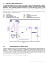
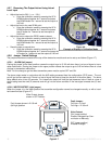
Figure 4.3
4.4.2 Threshold Level Parameter (THV) and Gain Setting (GS)
The threshold level and gain settings are used to fine tune the detection of products with different dielectric con-
stants, and to adapt to different probe configurations. THV is typically set between 1.0 to 1.8.
Note: Lower THV values make the transmitter less sensitive and higher THV values make the unit more sensitive to
lower dielectrics. GS is typically set to 2 or 4. GS = 1 is lower gain than GS = 2, and GS = 3 is lower Gain than GS =
4.
For probe configurations 1,2,3a, and 3b (Appendix G), with a dielectric constant above 10 use the factory default
settings THV=1.5, GS=2.
For probe configurations 4,5,6,7,8,9,10a, 10b, THV settings of 1.65 ± 0.15 are typical, depending on fluid dielectric
constant using GS = 4.