MT2000-0200-1 Rev f (10-2007)
DCN0160 5
2. OVERVIEW
2.1 Storage Information
If required, storage prior to installation should be indoors at ambient temperature, not to exceed the following:
Temperature range: -40 to 150 degrees F.
Humidity: 0 to 100% R.H. non-condensing.
2.2 Ambient Temperature
The MT2000 electronics temperature may not exceed 170°F / 77°C. For higher ambient temperatures, a high tem-
perature option extension is required. The probe process temperature shall not exceed the temperature stated in
the specifications for the given coupler.
2.3 Description & Principle of Operation
2.3.1 Direct Reflect Mode (standard)
The MT2000 is a 4-20mA loop powered Smart Level Transmitter, which is microprocessor based and is available
with HART or Honeywell DE digital output. It uses very low power microwave energy to determine the level of the
product being measured. In order to obtain optimum performance, it is important to understand the basic principle of
operation. The electronics housing is typically fitted with a special adapter “Coupler” serving as a process connection
and seal, and holding a solid rod or a cable. The rod or cable “Probe” hangs into the vessel and acts as a wave-
guide, i.e. the microwave energy stays concentrated around the probe and along its length, instead of being dis-
persed in a cone, as it would be if there was no probe.
A measurement cycle consists of the following:
1. A very short “pulse” of microwave energy is applied at the coupler, to the Probe.
2. The pulse travels along the length of the probe and when it encounters a discontinuity that is a dielectric con-
stant change, such as the product surface, some of the energy is reflected and travels back towards the coupler.
3. When the reflected energy reaches the coupler, it is sensed by the electronics. By measuring the time elapsed
between the initial pulse and the reflected one, the electronics can calculate the product level.
4. Since the microwave energy travels at the speed of light, one complete measurement cycle is made up of sev-
eral thousands of Pulses. The electronics uses Time Domain Reflectometry (TDR), a sampling technique to re-
construct a waveform duplicating the actual real time signal, but at a much lower speed, so that it can be proc-
essed by the microprocessor. This process can be compared to using the stroboscope effect as when observing
a piece of machinery turning at high speed with a strobe light.
5. The measurement cycles are made 10 times per second and processed by special filtering techniques, before
generating a current output proportional to the level of the product.
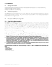
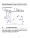
A simplified signal trace as seen on an oscilloscope (Figure 2-1) can be divided into four identifiable sec-
tions:
- Start Pulse.
- Coupler Reflection.
- Signal Reflection
- End of Probe Reflection


