


14 MT2000-0200-01 Rev f (10-2007)
DCN0160
4.4.3 Advanced Parameter Settings (cont’d)
• KO & KG
KO and KG parameters should only be changed during the replacement of an electronic module. Refer to
troubleshooting section
• LCH
For Devices configured to measure 0 at the end of the probe, this value defines the sensitivity of the Latching
feature. When this feature is enabled, and the detected signal extends past the end of the probe, the resulting
output is “latched” at 0, until the signal is again detected at the end of the probe. To disable this feature, set this
value to 0. If your application has a use for this feature, it is recommended that this value be set to “20” for RNG=1,
and “10” for RNG=2. If this value is not sufficient for the latching to take effect, lower this value as necessary.
• DRC
This feature is used in conjunction with the latching feature to determine the ease with which the output may become
unlatched. With this value enabled, the return signal must be detected above a certain point near the end of the
probe, identified by DRC. To disable this feature, set it to 0. To enable this feature, set the value to 40
(recommended). For turbulent processes, raise this value as necessary.
• ALD
Alarm Delay specifies the time (in seconds) an alarm condition will be ignored before the module enters its
alarm
condition (Hi or Lo, according to the FAULT HIGH/LOW jumper settings). Any condition generating an alarm (loss of
echo) must last longer than the specified amount of time before the transmitter’s output will be affected. During the
ALD timing period, the transmitter’s output is held steady at the last good signal. If the alarm condition clears before
ALD times out, the transmitter assumes normal operation. If the time delay is fulfilled without the alarm condition
clearing, the transmitter’s output goes immediately (by passing all output damping settings) into the fail condition
selected by the jumpers on the module face (Hi = 21 mA / Lo = 3.6 mA).
The primary use for this function is to compensate for applications that are typically low dielectric constant fluids and
that may be either boiling or flashing, causing a momentary loss of the signal echo. ALD will keep the process from
being upset, allowing the random condition to pass without impacting the transmitter’s mA output.
Notes:
• The DMP (transmitter’s output damping) parameter is bypassed when the alarm delay (ALD) time out.
• When the alarm condition clears, DMP is again bypassed and the output goes directly to the value gen-
erated by the level.
• Factory default setting is for ALD 2.0 seconds.
• RNG
All sensors with a measuring range less than 100 ft. / 30.5 m use the factory default value RNG=1 and do not require
changing this parameter. For a measuring range greater than 100 ft. / 30.5 m, RNG should be set to RNG = 2 by
accessing factory menu setup (Refer to menu chart).
• LTP
Sensor Trim "Lower Trim Point" defines a point on the sensor at which the display will indicate the value entered for
LTP. Refer to Appendices Section for Sensor Trim instructions.
• HTP
Sensor Trim "High Trim Point" defines a point on the sensor at which the display will indicate the value entered for
HTP. Refer to appendices Section for Sensor Trim instructions.
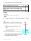
Note: When performing a Sensor Trim (Appendix A), one defines how the device makes measurements, in term of
Engineering Units, at 2 points on the sensor. All other level points on the sensor are derived from a linear formula
passing through LTP and HTP.