


ASSEMBLY
ASSEMBLY INSTRUCTIONS
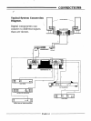
1. The processor is designed to sit directly on top of its companion
Power Supply. There is a mechanical interlock built into the front
feet of the processor and the chassis cover of the Power Supply.
The units are secured together in the rear by the power coupler.
2. Place the Power Supply on a clear work surface. Notice the
locking shoes at the front top of the Power Supply cover and the
lock pins at the rear top of the Power Supply cover.
3. Locate the Processor main unit. Carefully turn the unit over
to expose the chassis feet. Observe the design of the feet. The feet
have been carefully designed to slide into the shoes on the front
top of the Power Supply cover. The rear feet on the processor unit
fit directly over the pins protruding on the rear top of the Power
Supply cover. The rear feet are self-centering over the rear
protruding pins on the Power Supply cover.
4. Face the front of the Power Supply. Holding the front of the
Processor with both hands and the faceplate of the Processor
facing you, tilt the rear of the processor unit up and slide the unit
into the shoes on the top of the Power Supply cover. Once the feet
are in the cover shoes, gently set the rear of the processor down
on the Power Supply. The self-centering feet should center
themselves directly over the pins on the rear section of the Power
Supply cover.
PAGE 6