


systems to be easily coordinated. For more information on customizing the 12 V
trigger, see
Input Trigger, on page 39. Mono 1/8” mini connectors are used in
the following configuration: Tip = +12 V, Sleeve = GND.
Notes
When the Evolution Two is in the operational mode, the 12 V trigger provides 12 Volts
of DC output. When the component is in the stand-by mode or off, the DC output is
0 Volts.
A minimum of 30 mA is required to operate the 12 V trigger.
Consult the owner's reference of the components used in a custom installation to take
full advantage of the remote capabilities of the Evolution Two.
Link Control
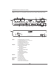
45 CAN Link
Each Evolution Two preamplifier chassis (1) has 2 RJ-45 link connectors, con-
nected in parallel. These are used to operate preamplifier channels in linked
mode.
For more information, see Connections Using CAN Link, on page 28,
Operation Using CAN Link, on page 31, and Link Control, on page 41.
Phono Stage Connector
46 Phono Power Port
Each power supply chassis (2) has a phono power port, for connecting the
preamplifier to a Krell KPE phono stage. Only one phono power port needs to
be connected to the KPE.
Power
47 DC Power Connector
Each pr
eamplifier channel is equipped with two DC power connectors that
connect the pr
eamplifier chassis and the power supply chassis, using the pr
o
-
vided 12-pin DC power cable.
48 IEC Power Cord Receptacle
The IEC power connector, located on the power supply chassis (2), is for use
with the provided IEC standard 15 amp AC power cord.
25