


4
1. Introduction
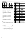
Max.
8mm
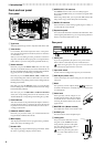
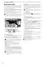
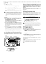
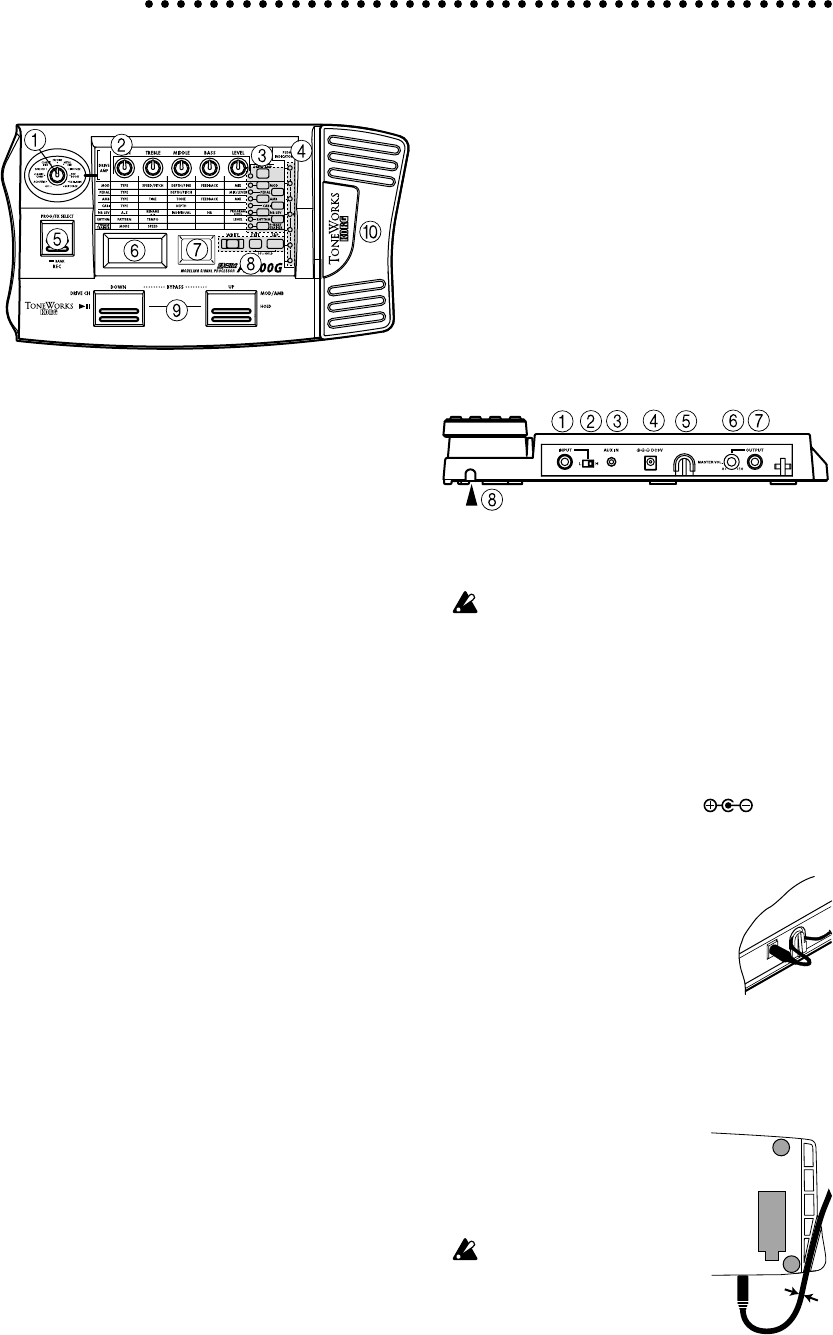
Front and rear panel
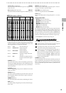
Front panel
1Type knob
This knob selects the type of Drive Amp effect that will be used.
2Value knobs
For each effect, these knobs adjust the values of the param-
eters assigned to the knobs. From the left, these are referred to
as value knobs 1—5.
When you are not editing an effect, parameters of the drive
amp effect used by the selected program are assigned to these
knobs. (Refer to p.9 "Drive Amp effect Quick Edit function.")
3Select switches
Each time you press the DRIVE·AMP switch, the drive amp
channels A and B will alternate, and will be in Edit mode. At
this time, the LED beside the switch will change between blink-
ing green (channel A) and blinking red (channel B).
Each time you press the MOD, PEDAL, AMB, or CABI switch,
the corresponding effect will be in edit mode (on) or off. The
LED beside the corresponding switch will also change between
blinking (lit) and dark.
Each time you press the NR LEV switch, you will alternate
between editing and on. The LED beside the switch will change
between blinking and dark.
Each time you press the RHYTHM or PHRASE TRAINER
switch, the corresponding function will be switched on/off.
The LED beside the corresponding switch will light or go dark.
4Pedal indicator
This shows the state of the pedal effect (the depth to which it is
pressed). When the tuner is operating, this shows the amount
of pitch deviation. In Phrase Trainer mode, this shows the re-
cording/playback time.
5PROG/FX SELECT switch
Each time you press this switch, you will alternate between
Program mode and Effect Select mode.
6Multi-display
This displays information such as program names, parameter
names and values, and editing icons.
7Number LED
This displays the program bank and program number. While
the Tuner is operating, it displays the note name.
8WRITE, EXIT, TAP switches
The WRITE switch is used to write an edited program.
By pressing the EXIT switch, you can return to Program mode
at any time.
When using a delay effect, you can press the TAP switch at the
tempo of the song to set the delay time automatically.
9DOWN, UP switches
These switches are used to select programs, bypass or mute, or
to switch the drive amp channel.
0Expression pedal
This controls the effect that is selected as the Pedal effect. After
advancing the pedal all the way, you can press the pedal more
firmly to switch the Pedal effect on/off.
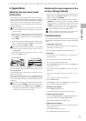
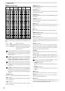
Rear panel
1INPUT jack
If you are using batteries, this jack acts as a power switch.
When a cable is connected, the power will be turned on.
Before turning the power on or off, be sure to turn down the
volume of any equipment that is connected.
2Input level switch
Set this switch according to the output of your instrument.
3AUX IN jack (stereo mini)
Connect the output (AUX OUT: analog) of your audio device
to this jack.
4DC9V
The separately sold AC adapter (DC9V ) can be con-
nected here. When this is connected, the power will be turned
on automatically.
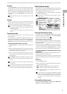
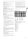
5Cable hook
If the separately sold AC adapter is con-
nected, hook the cable of the AC adapter
around this hook as shown below. When
removing the cable from the hook, do not
apply tension.
6MASTER VOL. (Master volume)
This adjusts the volume of the OUTPUT jack.
7OUTPUT jack
This also functions as the headphone jack.
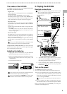
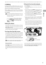
8 Cable guide
This prevents the cable that connects
the guitar to the AX100G from inter-
fering with the operation of the pedal.
Pass the cable through the guide as
shown in the diagram below.
When using the cable guide, please
use a cable whose diameter is 8 mm
or less.