64
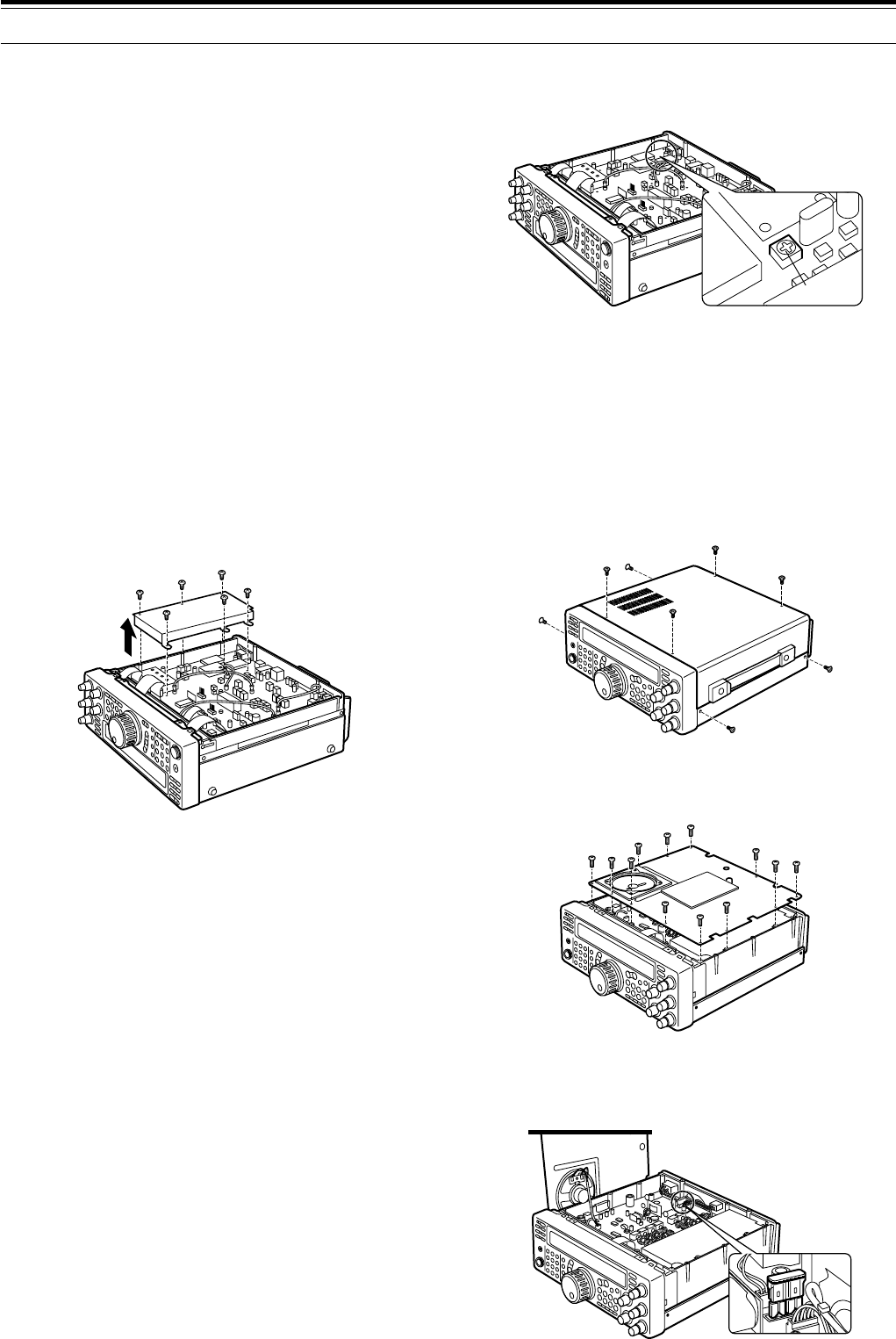
6 Adjust the TC500 trimmer to minimize the frequency
difference between the received 800 Hz tone and
the 800 Hz sidetone.
7 Re-install the protective cover on the PC board
(6screws).
8 Re-install the bottom case (8 screws).
ACCESSING THE INTERNAL FUSE
1 Remove the top case (8 screws) from the
transceiver.
2 Remove the 12 screws that fasten the inner cover to
the chassis.
3 Open the inner cover.
• Be careful not to damage the speaker cable
connected to the PC board.
16 MAINTENANCE
INTERNAL ADJUSTMENTS
REFERENCE FREQUENCY CALIBRATION
Note:
◆
The transceiver is adjusted at the factory prior to shipping.
Unless necessary, DO NOT perform this adjustment.
◆
If you have installed the optional SO-2 unit, you cannot perform
this adjustment.
1 Set the following on the transceiver:
• Mode: CW
• AF control: Center
• Menu No. 20 (CW RX pitch): 800 Hz
• IF SHIFT control: Center
• Receive bandwidth {page 38}: 600 Hz
• RIT function: OFF
• Break-in function (VOX): OFF
2 Remove the bottom case (8 screws) from the
transceiver.
3 Remove the protective cover installed on the PC
board (6 screws).
4 Tune in a standard frequency station such as WWV
or WWVH at, for example, 10.000 or 15.000 MHz.
• Adjust the Tuning control so that the display
reads the exact frequency of the station.
•You should hear a beat tone of approximately
800 Hz.
• For 800Hz:
faf = (fdisplay/20.000 x ∆freference) + 800Hz
where ∆freference is the shift from the 20MHz
reference frequency
5 Close your CW key and you will hear a transmit
sidetone of approximately 800 Hz.
• This sidetone produces a double beat tone when
it combines with the received signal.
• Adjust the AF control to hear the double beat
clearly.
• For 800Hz:
fsidetone = 800Hz ±50 ppm (= 800 ±0.04 Hz)
where ∆freference is the shift from the 20MHz
reference frequency
TC500
Fuse (4A)


