57
The following equipment is required for installing the
optional units.
• Large Philips screwdriver
• Small Philips screwdriver
• 25 W pencil soldering iron (for the SO-2 unit only)
REMOVING THE BOTTOM CASE
When installing the optional DRU-3A, VS-3, or SO-2
unit, remove the bottom case first.
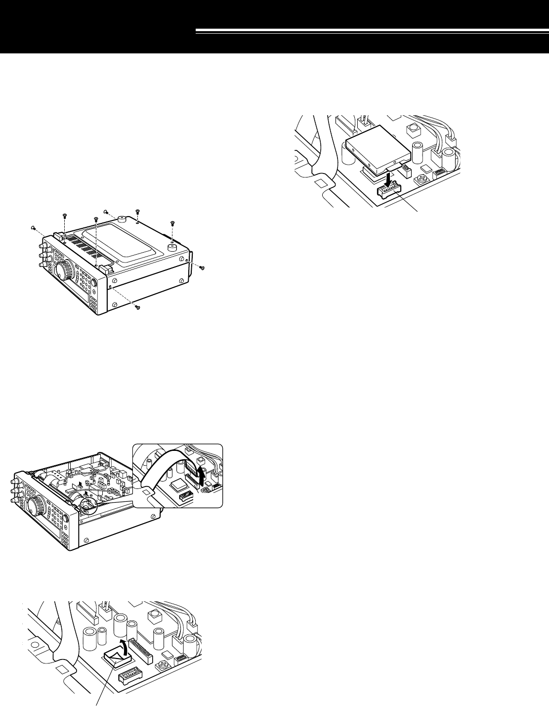
1 Remove the 8 screws.
2 Lift off the bottom case.
DRU-3A DIGITAL RECORDING UNIT
CAUTION:
SWITCH OFF THE POWER AND UNPLUG THE DC
POWER CABLE BEFORE BEGINNING INSTALLATION.
1 Remove the bottom case (8 screws).
2 Remove the flat cable from the CN15 connector.
3 Peel off the paper backing from the cushion installed
on the transceiver PC board.
INSTALLING OPTIONS
Cushion
CN15
CN17
4 Plug the DRU-3A connector (CN901) into the CN17
connector.
• The large IC on the DRU-3A must closely contact
the cushion on the PC board.
5 Reconnect the flat cable to the CN15 connector.
6 Replace the bottom case (8 screws).
DRU-3A


