


13
Chapter One : Connecting Your Devices
Connections
Connecting Your Cable TV or Satellite Tuner, continued
Do not plug in the receiver or devices to AC power until
you have connected all your devices.
This section focuses on the connections from your cable or
satellite tuner to the VR-5900. Please refer to your tuner’s
instructions for more detail about its connection jacks and
capabilities.
The instructions in this section show one of several pos-
sible variations on connecting your tuner. For further assis-
tance on optional configurations, contact your cable or sat-
ellite provider.
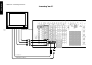
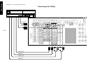
To Connect a Cable TV Tuner with a
Composite (RCA) Video Output:
1. Review the information under “Before You Begin” on
page 1. It contains important notes about the types of
video connections you can make.
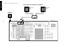
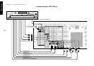
2. Connect the audio and video cables from the cable
tuner’s Audio and Video OUT jacks to the receiver’s
VIDEO2, VIDEO3, or VIDEO4 PLAY IN jacks as shown
to the left.
When component video cables are connected, the au-
dio and video cables of the cable TV tuner should be
connected to the VIDEO3 jacks of the receiver.
3. Go to “Noting Your Devices” on page 3 and note which
jack you used to connect your tuner. In addition, note
the brand name and model number of the tuner.
To Connect a Cable TV Tuner without a
Composite (RCA) Video Output:
1. Connect the audio cables from the cable tuner’s Audio
OUT jacks to the receiver’s VIDEO2, VIDEO3, or
VIDEO4 PLAY IN jacks as shown to the left.
2. Leave the cable tuner’s video out (RF jack) connected
directly to your VCR or TV (wherever you already have
it connected).
3. Go to “Noting Your Devices” on page 3 and note which
jack you used to connect your tuner. In addition, note
the brand name and model number of the tuner.
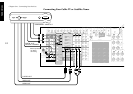
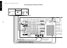
To Connect a Satellite Tuner:
1. Review the information under “Before You Begin” on
page 1. It contains important notes about the types of
video connections you can make.
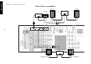
2. If your satellite tuner has a digital output jack, connect
a digital (optical or coaxial) cable between the satellite
tuner’s digital output jack and the receiver’s VIDEO2,
VIDEO3 or VIDEO4 digital input jack as shown in the
figure on the left.
The illustration shows two digital connections, one for
coaxial connection and one for optical connection. Your
Satellite tuner supports one or the other of these con-
nection methods—do not connect both.
3. Connect the audio and video cables from the satellite
tuner’s Audio and Video OUT jacks to the receiver’s
VIDEO2, VIDEO3, or VIDEO4 PLAY IN jacks as shown
to the left.
Note that the jack sets are linked, even though they are
not adjacent. You must connect all of the cables from
your satellite receiver to a linked jack set. For example,
if you connect the analog cables to VIDEO2 and the
digital optical cable to VIDEO3, your receiver will not
work correctly.
When component video cables are connected, the au-
dio and video cables of the cable TV tuner should be
connected to the VIDEO3 jacks of the receiver.
4. Go to “Noting Your Devices” on page 3 and note which
jack you used to connect your tuner. In addition, note
the brand name and model number of the tuner.
To play Dolby Digital or DTS-encoded software in multi-
channel configuration, you must connect the source device
via a digital connection.