


System description and usage
9
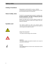
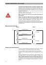
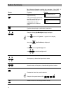
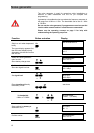
Downstream measurement: 47…860 MHz
Head-end (or transfer point) Transfer point (or terminal outlet)
Cable installation
with return path-capable amplifiers
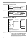
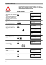
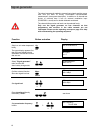
Upstream measurement: 4.0…80 MHz
Head-end (or transfer point) Transfer point (or terminal outlet)
Cable installation
with return path-capable amplifiers
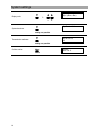
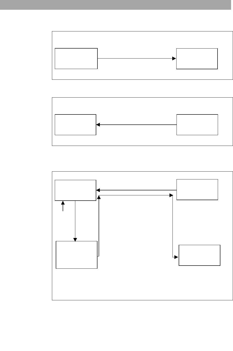
Comfortable upstream 4.0…80 MHz and
Downstream 47…860 MHz measurement
Cable installation
with return path-capable
amplifiers
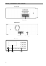
ext CVBS
Graphics RGB
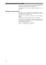
Presentation of upstream spectrum at head-end
Measurement of downstream spectrum
Upstream measurement:
The MVG 10 (1) sweeps the return path in the free frequency ranges.
The MSK 33 (1) receives the signals in MVG 10 – tracking mode.
The graphics from the MSK33 (1) are provided to the MVG10 (2) in
RGB (60 Hz) and transmitted to the MSK33 (2) on a free downstream
channel (attention: double-sideband modulation).
MVG10 (2)
Signal
sweep
generator
MVG10
Sweep
generator (1)
MSK33
receiver (2)
MSK 33
receiver
MVG 10
Sweep
generator
MVG 10
Sweep
generator
MSK 33
receiver
MSK33
receiver (1)