


System description and usage
8
System description and usage
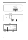
The MVG 10 Video Sweep Generator is designed to selectively sweep
and measure the forward path and return path of television cable
installations without interfering with the connected subscribers. The
required sweep ranges, channels and signal levels (36…100 dBµV)
can be programmed step-by-step. The channels can be set to various
standards (e.g. B/G etc.).
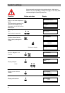
Frequency ranges that are in use must be left out so that the
subscriber reception is not disrupted.
Make a frequency and signal level plan before performing the
measurement!
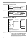
Before each frequency change, the MVG 10 transmits the next
reception frequency to the MSK 33 with a telemetric signal. In ranges
that are in use and which may not be sweeped, the MSK 33 can, as
an option, continue measurement in the same channel plan at
maximum scan speed. The MVG 10 pauses during this period.
The MSK measures the signal levels transmitted and presents them in
the spectrum. The measurement can also be printed out with the
integrated printer.
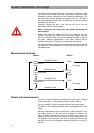
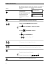
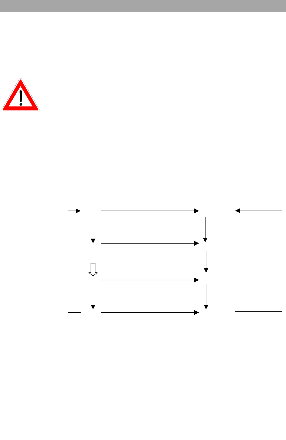
Measurement principle
MVG10 MSK33
Message FRQa+1
FRQa FRQa
Transmission
range Recording
Message FRQy
FRQx FRQx
Transmission-free quick
range sweep
Message FRQz
FRQy FRQy
Transmission
range Recording
Message FRQa
FRQz FRQz
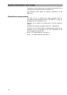
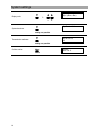
Return path measurement
The MVG 10 is also suitable for measuring the return path – terminal
outlet to head-end – in the frequency range 4.0 MHz…80MHz.
For this, the MSK 33 must be equipped with the return path option.
The MVG 10 Video Sweep Generator must be modulated with a video
signal.
Although measurement can be performed in cables that are in use,
the ranges that are in use may not be sweeped. In addition, the
MVG 10 signal generator can sweep in several partial ranges i.e.
ranges that are in use can be left out by the sweep generator so that
TV reception is not interrupted. The MVG 10 sweep generator informs
the MSK 33 of the next respective reception frequency over the RF
channel.