


7
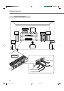
FM 75
COAXIAL
CAUTION :
SPEAKER
IMPEDANCE
816
+
–
+
–
+
–
+
–
AM LOOP
AM
EXT
ANTENNA
DIGITAL 2
(STB)
DIGITAL 1
(DVD)
DIGITAL IN
CENTER
SPEAKER
REAR SPEAKERS
RIGHT LEFT
FRONT SPEAKERS
RIGHT LEFT
SUBWOOFER
OUT
VCR
TV
DVD
STB
AV IN/OUT
AV IN
OUT
(REC)
IN
(PLAY)
TAPE
AUDIO
DIGITAL 1
(DVD)
DIGITAL 2
(STB)
DIGITAL IN
COAXIAL
DIGITAL OUT
A
B
OPTICAL
DIGITAL OUT
C
DVD Player
STANDBY
STANDBY ON
DOLBY
D
I
G
I
T
A
L
STB
LEFT
RIGHT
AUDIO
TAPE
IN
(PLAY)
OUT
(REC)
OUT IN
LEFT
RIGHT
AUDIO
Cassette Deck
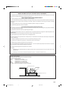
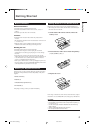
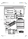
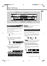
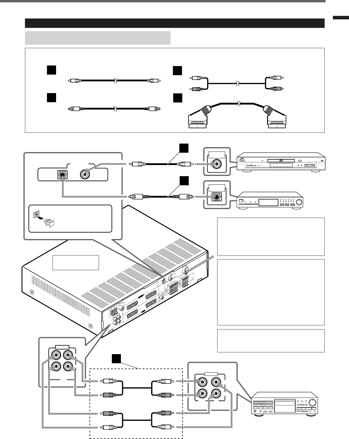
Connecting Audio/Video Components
Getting Started
Digital connections
Analogue
connections
Turn the power off to all components before connections.
Connecting cords are not supplied with this unit. Use the cords supplied for the other components or purchase them at an audio
or electric appliance store.
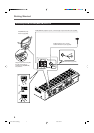
A
B
C
D
Optical digital cord
Coaxial digital cord Audio cord
SCART cable
TO BE CONTINUED TO THE NEXT PAGE
Before connecting an
optical digital cord,
unplug the protective
plug.
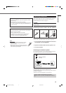
RX-E100R
Illustrations of the input/output terminals
are typical examples.
When you connect other components, refer
also to their manuals since the terminal
names actually printed on the rear vary
among the components.
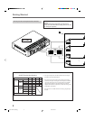
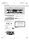
• When shipped from the factory, the DIGITAL
IN terminals have been set for use with the
following components.
– DIGITAL 1 (coaxial): For DVD player
– DIGITAL 2 (optical): For STB
If you connect other components, change the
digital input (DIGITAL IN) terminal setting
correctly. See “Setting the Digital Input
Terminals” on page 13.
• Select the digital input mode correctly.
See “Selecting the Analogue or Digital Input
Mode” on page 13.
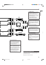
If you connect a sound-enhancing device such
as a graphic equalizer between the source
components and this unit, the sound output
through this unit may be distorted.
EN01-09.RX-E100RSL[B]_f 01.3.8, 2:49 PM7