


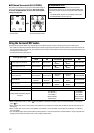

AV COMPU LINK
remote control
system
The AV COMPU LINK remote control system allows you to
operate JVC’s video components (TV, DVD player*, and
VCR) through this receiver.
This receiver is equipped with the AV COMPU LINK-III, which
has added a function to operate JVC’s video components
through the component video jacks. To use this remote
control system, you need to connect the video components
you want to operate, following the diagrams below and the
procedures on page 46.
• Refer also to the manuals supplied with your video
components.
* “DVD player” on pages 45 and 46 can be replaced with “DVD
recorder.”
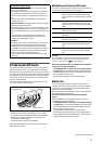
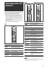
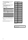
7 Connections 1: AV COMPU LINK connection
IMPORTANT:
• The AV COMPU LINK remote control system cannot control
the DBS tuner connected to the DBS IN jacks.
• To use the AV COMPU LINK remote control system, select
“OHTER” for the video output setting (see page 34);
otherwise, the AV COMPU LINK remote control system is
restricted to turning the video component on and off. See
“Automatic power on/off” on page 46.
Monaural mini-plugs
(not supplied)
VCR
DVD player
Monaural mini-plugs (not supplied)
TV
NOTES
• When connecting the receiver and a TV with the AV COMPU LINK
EX terminal by using a component video cable, you cannot use
Automatic selection of TV input mode (see page 46).
• When connecting only the VCR or DVD player to this receiver,
connect it directly to the receiver using a cable with the monaural
mini-plugs.
• You can connect only the TV with AV COMPU LINK EX or AV COMPU
LINK-III terminal to the AV COMPU LINK-III terminal.
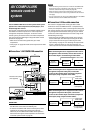
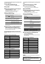
7 Connections 2: Video cable connection
This receiver is equipped with three types of the video
terminals as well as the HDMI terminals—composite video,
S-video, and component video—and the signals coming into
this receiver through one type of video terminals can output
only through the terminal of the same type. So you need to
connect the video components to this receiver using one of
the following three ways.
• When using the AV COMPU LINK remote control system,
set the video input and video output setting for the DVD
player and the VCR correctly (see “Selecting the video
input setting” on page 21 and “Selecting the output video
signals—VIDEO OUTPUT” on page 34); otherwise, the
correct input for this receiver will not be selected on the TV.
Case 1:
When connecting the source equipment to the receiver
through the S-video terminals, connect this receiver to
the TV video input 1 terminal using S-video cables.
Case 2:
When connecting the source equipment to the receiver
through the composite video jacks, connect this
receiver to the TV video input 2 terminal (composite
video input) using composite video cables.
Case 3:
When connecting the source equipment to the receiver
through the component video jacks, connect this
receiver to the TV video input 2 terminals (component
video input) using component video cables.
Source
equipment
RX-D411S
RX-D412B
TV
S-video cable
TV video input 1
Source
equipment
RX-D411S
RX-D412B
TV
Composite
video cable
TV video input 2
(Composite)
Source
equipment
RX-D411S
RX-D412B
TV
Component
video cable
TV video input 2
(Component)
45