


11
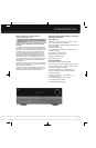
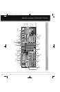
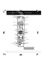
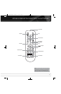
REAR - PANEL CONNECTIONS
Fan Vents: This area contains vents used by the AVR 7550HD’s
fan to cool the system. Maintain a clearance of at least 3 inches
from the nearest surface to avoid overheating the unit. It is normal
for the fan to remain off at most normal volume levels. An automatic
temperature sensor turns the fan on only when it is needed.
IMPORTANT NOTE: Never block the fan vents, as doing
so could allow the AVR to overheat to dangerous levels.
Zone 2 Video Output: Connect this composite video jack
to a video display located in the remote zone of a multizone system.
When the multizone system is in use, viewers in the remote zone
will be able to see the AVR’s on-screen text menus and any available
source video, as long as the source is connected to a Composite
Video Input, and that input is specified for that source in the Zone 2
Video setting of the Info Settings menu.
Composite and S-Video 1, 2 and 3 Video Inputs:
Use these jacks to connect your video-capable source components
(e.g., VCR, DVD player, cable TV box) to the receiver. Use only one
type of video connection for each source.
Composite and S-Video 2 Outputs: Connect one of
these analog video outputs to the composite or S-video inputs of
a recording device. A signal is available at these outputs whenever
an analog video source is playing.
Composite and S-Video Monitor Outputs: If any
of your sources use composite or S-video connections, connect one
or both of these monitor outputs to the corresponding inputs on
your video display. If your video display is equipped with HDMI or
component video inputs, these connections are unnecessary, as the
AVR 7550HD will convert the composite or S-video source signal
to the correct format for a single video-cable connection to the TV.
Component Video 1, 2 and 3 Inputs: If a video
source has analog component video (Y/Pb/Pr) capability, and if you
are not using an HDMI connection, connect the component video
outputs of the source to one of the sets of component video inputs.
Do not make any other video connections to that source.
Component Video Monitor Outputs: If you are
using one of the Component Video Inputs and your television or
video display is component-video-capable (but does not have
HDMI), connect these jacks to the video display.
NOTES:
• Due to copy-protection restrictions, there is no output at
the Component Video Monitor Outputs for copy-protected
sources.
• Composite and S-video signals are upscaled to as high as
1080i and available at these outputs. If your video display’s
best connection is component video, it is the only video
connection required from the AVR to the display.
AM and FM Antenna Terminals: Connect the included
AM and FM antennas to their respective terminals for radio reception.
Preamp Outputs: Connect these jacks to an external
amplifier if more power is desired. The Surround Back/Zone 2
Preamp Outputs may be used with an external amplifier to power
the remote zone of a multizone system.
A-BUS Port: Use a Category 5/5e cable to connect this port to
optional A-BUS equipment for multizone operation. When the A-BUS
system is used, it is possible to have a full 7.2-channel system in
the main listening room at the same time the multizone system is
in use.
Front, Center and Surround Speaker Outputs:
Use two-conductor speaker wire to connect each set of terminals
to the correct speaker. Remember to observe the correct polarity
(positive and negative connections).
Surround Back/Zone 2 Speaker Outputs: These
speaker outputs are used for the surround back channels in a
7.2-channel home theater, or may be reassigned to a remote room
for multizone operation.
Switched AC Accessory Outlet: You may plug the
AC power cord of one source device into this outlet, and it will turn
on whenever you turn on the receiver. Do not use a source that
consumes more than 50 watts of power.
AC Power Input: After you have made all other connections,
plug the AC power cord into this receptacle and into an unswitched
wall outlet.
AVR 7550HD OM.qxd 2/25/09 11:52 AM Page 11