


10
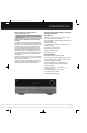
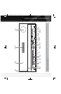
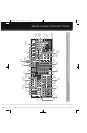
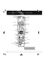
REAR - PANEL CONNECTIONS
6-/8-Channel Inputs: Connect the multichannel analog
audio outputs of a non-HDMI player (DVD-Audio, SACD
™
, Blu-ray
Disc
™
or HD-DVD, or any other external decoder) to these jacks.
Coaxial 1/2/3 and Optical 1/2/3 Digital Audio
Inputs: If a source has a compatible digital audio output, and
if you are not using an HDMI connection for audio for the device,
connect it to one of these jacks to hear digital audio formats, such
as Dolby Digital, DTS and linear PCM. Use only one type of digital
audio connection for each source.
Coaxial and Optical Digital Audio Outputs: If
a source is also an audio recorder, connect one of the Digital Audio
Outputs to the recorder’s matching input for improved recording
quality. Only PCM digital audio signals are available for recording.
Both coaxial and optical digital audio signals are available at either
Digital Audio Output.
XM Antenna Jack: Plug in an XM Connect-and-Play or
Mini-Tuner antenna module here.
Network Jack: Plug in an RJ-45-compatible cable that con-
nects to a personal computer (PC), router or Internet access. When
connected to a PC, the AVR 7550HD is capable of playing audio and
JPEG files stored on the PC. When connected to the Internet, the
AVR 7550HD may be used to enjoy Internet Radio. See pages 36
and 37 for more information.
RS-232 Serial Port: This bi-directional port may be used
to control the AVR 7550HD using an RS-232 serial control link to a
compatible computer or programmable remote control system. Due
to the complexity of programming RS-232 commands, connections
and programming for control purposes should be performed by a
qualified custom installer.
Trigger 1 and 2 Outputs: Connect these control jacks
to the trigger input jack of an external component, such as an audio
power amplifier, that you want to power on any time the AVR 7550HD
is turned on, without using the AVR’s Switched Accessory Outlet for
power. When this connection is used, the AVR 7550HD will automat-
ically send a low-voltage signal to the connected device that trig-
gers it to turn on when the AVR 7550HD is on, and off when the
AVR 7550HD is placed in the Standby Mode. The connected compo-
nent must respond to 6-volt presence as the control signal.
The Trigger 2 Output may be programmed to transmit its signal only
when certain of the AVR’s source inputs are selected. For example,
to lower a screen when watching a DVD movie, but not while listen-
ing to the tuner, connect the Trigger 2 Output to the screen and pro-
gram it to be on when the DVD source is selected, but off when the
AM, FM or XM bands are in use. See the Initial Setup section for
more information on programming this setting in the Info Settings
menus for each source.
Zone 2 Infrared (IR) Input: Connect a remote IR receiver
located in the remote zone of a multizone system to this jack to
control the AVR (and any source devices connected to the Remote
IR Output) from the remote zone.
Remote Infrared (IR) Input and Output: When the
remote IR receiver on the front panel is blocked, connect an optional
IR receiver to the Remote IR Input jack. The Remote IR Output may
be connected to the Remote IR Input of a compatible product to
enable remote control through the AVR.
Remote IR Carrier Output: This output is similar in
function to the Remote IR Output, with the difference that this jack
outputs the full infrared signal as received by the AVR’s IR sensor
or the Remote IR Input, while the Remote IR Output jack outputs a
“stripped” signal that has no carrier frequency.
HDMI Inputs and Output: HDMI (High-Definition
Multimedia Interface) is a connection for transmitting digital audio
and video signals between devices. Connect up to four HDMI-
equipped source devices to the HDMI inputs using a single-cable
connection.
When you connect the HDMI Output to your video display, the
AVR 7550HD will automatically transcode analog video signals to
the HDMI format, upscaling to as high as 1080p.
NOTES: When connecting a DVI-equipped display to one of
the HDMI Outputs:
• Use an HDMI-to-DVI adapter.
• Make sure the display is HDCP-compliant. If it isn’t, do not
connect it to an HDMI Output; use an analog video connection
instead.
• Always make a separate audio connection.
Analog 1 – 5 Inputs: Connect the left and right analog
audio outputs of a source device to any of these inputs. These
inputs may be paired with any video inputs.
NOTES:
• The Analog 3 and 4 inputs are each associated with a set
of outputs. Consider using these connectors for an audio or
video recorder.
• You may optionally connect a source to both an analog and
digital audio input. This is useful for making recordings, for
multizone applications or simply as a backup.
Analog 3 and 4 Outputs: Connect either of these analog
audio outputs to the analog audio inputs of a recording device.
A signal is available at these outputs whenever an analog audio
source is playing.
Zone 2 Audio Outputs: Connect these jacks to an external
amplifier to power the speakers in the remote zone of a multizone
system.
Subwoofer 1 and 2 Outputs: If you have a powered
subwoofer with a line-level input, connect it to the Subwoofer 1
Output. For improved performance, connect a second powered
subwoofer to the Subwoofer 2 Output.
The Bridge II Input: Connect the included Harman Kardon
docking station to this input for use with most docking
iPod models, 4G and later (not included). Turn the receiver off
(Standby mode) when connecting The Bridge II.
AVR 7550HD OM.qxd 2/25/09 11:52 AM Page 10