


ST72F324L, ST72324BL
6/151
1 INTRODUCTION
The ST72F324L and ST72324BL devices are
members of the ST7 microcontroller family de-
signed for the 3V operating range. They can be
grouped as follows:
– The 32-pin devices are designed for mid-range
applications
– The 44-pin devices target the same range of ap-
plications requiring more than 24 I/O ports.
All devices are based on a common industry-
standard 8-bit core, featuring an enhanced instruc-
tion set and are available with FLASH or ROM pro-
gram memory.
Under software control, all devices can be placed
in WAIT, SLOW, ACTIVE-HALT or HALT mode,
reducing power consumption when the application
is in idle or stand-by state.
The enhanced instruction set and addressing
modes of the ST7 offer both power and flexibility to
software developers, enabling the design of highly
efficient and compact application code. In addition
to standard 8-bit data management, all ST7 micro-
controllers feature true bit manipulation, 8x8 un-
signed multiplication and indirect addressing
modes.
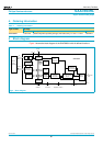
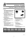
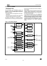
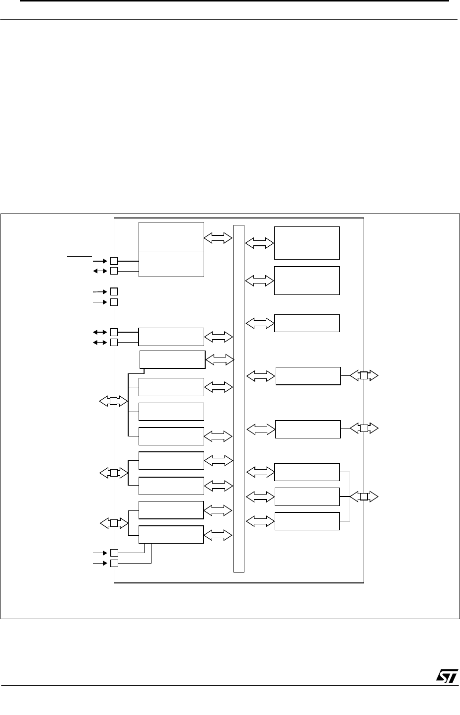
Figure 1. Device Block Diagram
8-BIT CORE
ALU
ADDRESS AND DATA BUS
OSC1
V
PP
CONTROL
PROGRAM
(8K - 60K Bytes)
V
DD
RESET
PORT F
PF7:6,4,2:0
TIMER A
BEEP
PORT A
RAM
(384 - 2048 Bytes)
PORT C
10-BIT ADC
V
AREF
V
SSA
PORT B
PB4:0
PORT E
PE1:0
(2 bits)
SCI
TIMER B
PA7:3
(5 bits on J devices)
PORT D
PD5:0
SPI
PC7:0
(8 bits)
V
SS
WATCHDOG
OSC
OSC2
MEMORY
MCC/RTC/BEEP
(4 bits on K devices)
(5 bits on J devices)
(3 bits on K devices)
(6 bits on J devices)
(2 bits on K devices)
(6 bits on J devices)
(5 bits on K devices)
3
DVD47 harman/kardon
88