


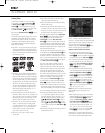

DISASSEMBLY PROCEDURES (DVD27)
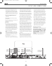
<1> TOP-COVER (21) REMOVAL
1. Remove 4 screws and then remove the Top-cover.
<2> FRONT PANEL ASS’Y REMOVAL
1. Remove the Top-cover, referring to the previous step<1>.
2. Disconnect the lead wire (BN72-32p) on the Fip PCB (37-1) from connector (CN72) on the Input PCB (39-1)
3. Disconnect the lead wire (BN80-11P) on the Fip PCB (37-1) from connector (CN80) on the Main PCB (38-1).
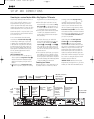
4.Disconnect the lead wire (BN16-6P) on the Tone PCB (37-3) from connector (CN16) on the Connect PCB (37-7).
5. Disconnect the lead wire (BN41-6P) on the Tone PCB (37-3) from connector (CN41) on the Video PCB (40-1).
6. Disconnect the lead wire (BN18-5P) on the Digital input PCB (37-8) from connector (CN18) on the Input PCB (39-1).
7. Disconnect the lead wire (BN81-8P) on the Fip PCB (37-1) from connector (CN81) on the Trans PCB (40-5).
8. Disconnect the lead wire (BN15-8P) on the Fip PCB (37-1) from connector (CN15) on the Download PCB (37-9).
9. Remove 1 screw(S10) and then lead wire (JW82-2P) on the Phone PCB (37-4).
10.Remove 1screw(S10) and then lead wire (JW84-1P) on the Tone PCB (37-3)
10. Remove 10 screws (S1) and then remove the Front Panel ASS’Y.
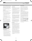
<3> TONE PCB (37-3) REMOVAL
1. Remove the Top-cover, referring to the previous step<1>.
2. Remove the Front Panel ASS’Y, referring to the previous step<2>.
3. Pull out the Volume Knob ASS’Y & 3 Rotary Knobs (5).
4. Remove 10 screws (S2,S14), and then remove the Tone PCB (37-3).
5. Disconnect the lead wire (BN84-5P) One the Tone PCB (37-3) from connector (CN84) on the
Fip PCB (37-1)
<4>PHONE PCB (37-4) REMOVAL
1. Remove the Top-cover, referring to the previous step<1>.
2. Remove the Front Panel ASS’Y, referring to the previous step<2>.
3. Disconnect the lead wire (BN85-2P) on the Fip PCB (37-1) from connector (CN85) on the Phone PCB (37-4)
4. Remove 2 screws (S2,S3) and then remove the Phone PCB (37-4)
.
<5>POWER LED PCB (37-6) REMOVAL
1. Remove the Top-cover, referring to the previous step<1>.
2. Remove the Front Panel ASS’Y, referring to the previous step<2>.
3. Remove 2 screws (S2) and then remove the Power led PCB (37-6).
4. Disconnect the lead wire (CN88) from connector (BN88-4P) on the Fip PCB (37-1).
<6>FIP PCB (37-1) REMOVAL
1. Remove the Top-cover, referring to the previous step<1>.
2. Remove the Front Panel ASS’Y, referring to the previous step<2>.
3. Remove the Tone PCB (37-3), referring to the previous step<3>.
4. Remove the Phone PCB (37-4), referring to the previous step<4>.
5. Remove the Power led PCB (37-6), referring to the previous step<5>.
6. Remove 6 screws (S2) and then remove the Fip PCB (37-1)
<7>TUNER MODULE (42) REMOVAL
1. Remove the Top-cover, referring to the previous step<1>.
2. Disconnect the connector (CON1-Card cable) from connector (CN13) on the Input PCB ASS’Y(39-1).
3. Remove 2 screws (S8) and then remove the Tuner Module (42).
DVD47 harman/kardon
20