


AM5888S
Motor Driver ICs
A
A
M
M
t
t
e
e
k
k
S
S
E
E
M
M
I
I
C
C
O
O
N
N
D
D
U
U
C
C
T
T
O
O
R
R
S
S
F
F
e
e
b
b
2
2
0
0
0
0
5
5
V
V
1
1
.
.
2
2
- 5 -
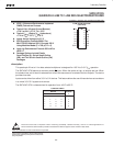
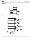
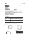
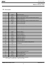
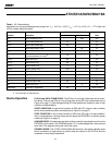
Pin description
PIN No Pin Name Function
1 VINFC Input for focus driver
2 TRB_1 Connect to external transistor base
3 REGO2 Regulator voltage output, connect to external transistor collector
4 VINSL+ Input for the sled driver
5 REGO1 Regulator voltage output, connect to external transistor collector
6 FWD Tray driver forward input
7 REV Tray driver reverse input
8 Vcc1 Vcc for pre-drive block and power block of sled and tray
9 VOTR- Tray driver output (-)
10 VOTR+ Tray driver output (+)
11 VOSL+ Sled driver output (+)
12 VOSL- Sled driver output (-)
13 VOFC- Focus driver output (-)
14 VOFC+ Focus driver output (+)
15 VOTK+ Tracking driver output (+)
16 VOTK- Tracking driver output (-)
17 VOLD+ Spindle driver output (+)
18 VOLD- Spindle driver output (-)
19 Vcc2 Vcc for power block of spindle, tracking and focus
20 NC No Connection
21 VCTL Speed control input of tray driver
22 GND Ground
23 VINLD Input for spindle driver
24 NC No Connection
25 TRB_2 Connect to external transistor base
26 VINTK Input for tracking driver
27 BIAS Input for reference voltage
28 MUTE Input for mute control
Notes) Symbol of + and – (output of drivers) means polarity to input pin.
(For example, if voltage of pin1 is high, pin14 is high.)
DVD47 harman/kardon
57