


90
10
11
12
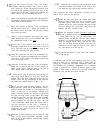
Select the plastic encased relay, the longer
L-shaped mounting bracket, and 2 sets of hard-
ware. Insert the screws through the bracket with
the bracket foot pointing away from the lugs at the
opposite end of the relay. ‘lighten this hardware
se-
curely, but do not risk breaking the plastic.
Select 2 sets of hardware and mount the relay near the 2
red terminals, with the bracket facing front. Install the
screws from below the chassis.
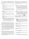
Select the 2 shorter L brackets, 4 sets of hardware,
and the circuit board PC-9. Mount the brackets on
the circuit side of the board, with the feet pointing
away from the board.
Select 2 sets of hardware and install the circuit
board between the line cord and terminal RB, with
the components facing to the rear.
13
0
Select the 7-lug terminal strip and 2 sets of
hardware.
Install it at the two inner holes in front of
PC-9. The hole near the right chassis edge is not
used. The mounting feet face forward.
14
0
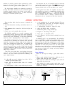
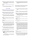
Select the single fuse clip and a set of hardware. In-
stall it in the single hole between the two “dimples”
at the front of the chassis. The dimples prevent the
clip from turning too far.
15
0
Select the 2 dual fuse clips and 4 sets of hardware.
Install one of these in the pair of holes nearest the
center of the chassis, and the other in the pair of
holes aligned with it near the left edge.
16
q
Select the
3/4”
long
#6
screw and a nut, and the rec-
tifier diode block which has four lugs. Install the
rectifier DB in the front center hole nearest the fuse
holders. Note the lug positioning in the diagram,
and check the marked location of the + lug.
17
I-J
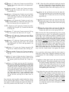
Select the two round capacitor brackets, the two
large capacitors, and 8 sets of
#6
hardware. Place a
bracket around the bottom of each capacitor and
fasten it with one set of hardware through each
clamp. Note the direction of insertion of the screw
for easy servicing access in the future. The clamp
should be snug, but not tight. Place each assembly
so the clamping screws are accessible from the
front at locations CL and CR, and secure each with
3 sets of hardware. Then loosen the clamps and ro-
tate the capacitors so that each + terminal is
positioned as in the diagram. Make sure the
capacitors are seated against the chassis and
tighten both clamps.
18
0
Select the 4 plain connecting lugs and four
l/4”
long
large screws with lockwashers attached. Install
these on top of the capacitors with the lugs pointing
as in the diagram.
19
q
Select the two 2 amp fuses and install them in the
round fuse holdders on the back of the chassis. This
will keep the caps from being loosened and lost.
This completes the basic mechanical assembly of the
chassis. Set it aside for the present.
20
0
Select the large front plate, the smaller front panel
with the edges turned back, the two handles, and
four
#lO
screws. With the power switch cutouts
aligned, place the screws through the panel from
the rear, through the front plate, and secure the
handles. Set this assembly aside.
21
0
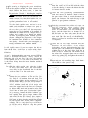
Select the amplifier module. Handle it with care!
The fan is mounted on the front of the module, with
a foam gasket on the rear. On the bottom, two
thermal sensors for the fan, and two safety thermal
breakers are already mounted on the heat sinks.
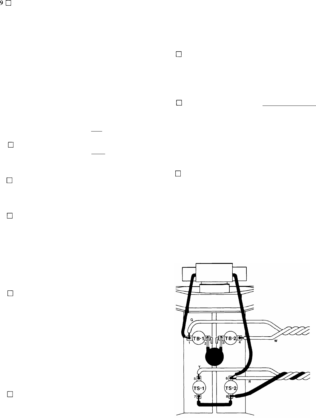
With the module upside down, and the fan away
from you (to keep the left channel on the left, for
consistency) cut the right fan lead to
5-3/4”,
strip it
l/4”,
and connect it to TS2 lug
#6.
22
0
Cut the left fan lead to
4”,
strip it l/4”, and connect it
to
TBl
lug
#l.
A soldering iron will be used regularly from now on. Be
sure you wipe its tip frequently with a damp cloth or
sponge, as a bright tip will make connections easier with
less likelihood of overheating components. If it is difficult
to heat a connection in a couple of seconds, apply a small
amount of fresh solder to the tip so it can flow around the
connection and provide good heat transfer.
PC-9