


97
0
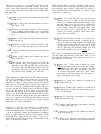
Select the
.Ol
mfd disc capacitor and trim each lead
to
3/4".
Strip two
1/2"
lengths of insulation from a
piece of heavy wire, and install these on the
capacitor leads. Connect one lead to DB lug
#l.
(S-3). Connect the other lead to DB lug
#4.
(S-2).
98
0
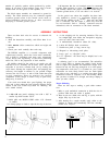
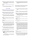
Select the power switch and the
.OO5
mfd disc capacitor.
With
the
red window (or, on some switches, the
#3
lug,
or
the separate
lug)
of the switch to your right,
temporarily
slide the white wire’s spade lug part way
onto the left switch lug. Slide the line cord’s spade lug
part way onto the middle switch lug. This simply makes
it easier to attach the capacitor to these two spade lugs.
Cut each capacitor lead to one inch (some freedom of
movement is desirable), wrap one lead around the shaft
of each spade lug, and solder each. Then carefully
disconnect the wires from the switch.
99
0
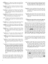
Install the fuses. The 15 amp slo-blo fuse goes in the
single fuse clip near the power switch. The four 10
ampere fuses, with the
thicker elements,
go into the
two dual fuse clips on the chassis. If you have not
already placed fuses in the speaker fuse holders on
the back panel, install the 2 ampere size, for these
will give good protection to most speakers. A pair
of 5 ampere fuses are also included for the speaker
holders, in
the event your needs require very high
powers. However, for steady state test signals at
the full amplifier capabilities, even larger fuse sizes
will be needed in the speaker fuse holders.
Now you should make a last check of all the solder connec-
tions. Look closely for possible bare wire shorts, Check
for secure hardware
-especially that on the output termi-
nals. Check that wires are not lying on top of the power
resistors on the 7-lug terminal strip. Remove all pieces of
solder and wire clippings from the chassis.
Three wire ties have been included in the kit which you
may wish to install around groups of wires to make your
finished amplifier look neat. Because it is desirable that
the ground wires which connect between CL and CR be
kept close together, we suggest using one tie at the base of
the capacitors.
100
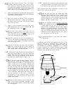
0
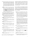
Select the front panel assembly and the power switch,
and make sure that the power switch is oriented with the
red window
(#3
lug, or separate lug) to the right, or
nearest edge. The switch is a press snap fit from the
outside of the panel.
101
0
Select 4 sheet metal screws, and bring the front
panel to its approximate position. Carefully attach
the 3 wires to the switch lugs: white to the left;
green to the right. Push the lugs fully on, and as-
semble the front panel to the chassis. NEVER AT-
TEMPT TO PICK UP THE AMPLIFIER BY THE
HANDLES IF THE COVER IS NOT SCREWED
IN PLACE.
102
0
Select the remaining sheet metal
screws
and
the
cover. Before closing up the unit, plug it in
and
check to see that the fan turns. Because it normally
operates at low voltage for low speed, a new fan
may need a bit of encouragement at first. Any stiff-
ness is normally overcome after a few minutes op-
eration. Once you
are
sure it turns on each time the
power switch is turned on, secure the cover.
103
0
Peel off the backing from the serial number label,
and
affix
it to the bottom of the chassis.
CONGRAI’ULATIONS!
YOU HAVE COMPLETED ONE OF THE FINEST
AUDIO AMPLIFIERS EVER DESIGNED.
ENJOY ITS SUPERB SOUND.
IF PROBLEMS ARISE
If you are certain the problem lies in the power amplifier,
check first to see that the red pilot lamp is lighted. If it is
blinking at about 3 times a second, this indicates that the
thermal safety breaker on one channel has shut down the
amplifier because of excessive temperature. In this case,
the exhaust air will be warm. After a few minutes of cool-
ing, the amplifier will commence operation automatically.
If it shuts down again, and the amplifier has sufficient ven-
tilation, the malfunction is either internal, or is the result of
an excessive (and possibly inaudible) input signal.
If the lamp is not lighted at all, the main fuse in the single
fuse clip inside the chassis at the front is probably open. If
a replacement 15 ampere, slo-blo fuse also blows, the
amplifier needs service, and there is a power supply prob-
lem. If the relay will not close (no signal at the output, with
an input signal) check for excessive DC offset (over 1.8
volts) from either channel at locations 7 or 8 on PC-9-the
small relay circuit board. This indicates a defective
amplifier channel, requiring competent service. If there is
no indication of excessive offset, the fault is in the relay or
on the PC-9 circuit board.
On rare occasions with some arm/cartridge combina-
tions, very high signal levels at subaudible frequencies
may cause the relay to cut off the output briefly, because
the sensing circuit sees this as DC offset.
If this is annoy-
ing, and you are willing to accept a little less relay protec-
tion, you you can change R107 and R108 to a higher value.
These are now each 39000hms (orange, white, red) and are
located above the IC on the small circuit board PC-9A. We
suggest 4700 ohms as the next step. At the other extreme,
it is possible to increase the sensitivity so that the relay
would protect the speaker if a stylus were dropped on the
record, but then it might be activated by powerful low fre-
quency transients.
If the fan does not turn, or makes a ticking noise, make
sure it is properly centered in its supports, and that ship-
ping abuse has not twisted it so the blades are rubbing the
housing. Moderate pressure on the struts will
recenter
it.
14