


40
0
Prepare two 9” white wires. Connect one to eyelet
52
q
Select the spade lug and connect it to the free end of
#8 of the left board. (S). Connect the other to
the white wire from LT lug 6. Place this wire to the
eyelet #6. (S). Bend these toward the bottom, and
left, and twist it lightly together with the green wire
twist them together.
from
LT
lug 3.
41
0
Prepare a 3” white wire and connect it to eyelet #3.
(S).
42
0
Prepare a 6” green wire and connect it to eyelet
#10
(S). Set the module aside temporarily.
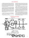
When connecting wires to the PC-9 circuit board note that
the eyelets on this board are numbered in the reverse direc-
tion from the lug numbers on the terminal strip.
CHASSIS WIRING
43
0
Select the chassis and the
.39
mfd capacitor. Trim
each lead to
1/2".
Connect one lead of the capacitor
to
LT
lug #3. Connect the other lead to lug #4.
44
I-J
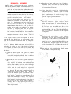
Select the silicon diode. Note that one end has a
53
q
Prepare a
2 3/4"
red wire. Connect one end to PC-9
eyelet #8. (S). Connect the other end to relay RY
lug #7.
54
0
Prepare a 2” yellow wire. Connect one end to PC-9
eyelet #7. (S). Connect the other end to RY lug #9.
stripe for identification. Connect the striped end to
LT
lug #3. Connect the other lead to lug #2.
45
0
Select the
1/2
watt 1 megohm (brown-black-green)
resistor. Trim each lead to
l/2”
and connect one lead
to LT lug
#2.
(S-2). Connect the other lead to LT lug
#l.
55
/J
Strip a
1-1/2“length
of heavy wire bare. Connect one
end to large capacitor CL lug X2. (S). Connect the
other end to CR lug #3. (S). Be very
sure
that these
connections are well soldered because they will
carry considerable current.
56
0
Prepare an
8-1/2”
red wire. Connect one end to PC-9
eyelet #6. (S).
46
0
Prepare a
7-1/2”
white wire. Connect one end to
LT
lug
#1.
(S-2). Connect the other end to fuse clip FC
lug
#l.
(S).
57
0
Prepare a 19’ black wire. Connect one end to PC-9
eyelet #5. (S).
47
0
Prepare a 12”green wire. Connect one end to
LT
lug
#3. (S-3).
58
q
Prepare a 9” yellow wire. Connect one end to PC-9
eyelet #4. (S).
48
0
Select one of the spade lugs. Connect it to the other
end of the green wire just attached to lug #3. (S).
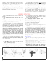
The proper way to connect one of the spade lugs to
the wire is to bend the shorter, wider set of tabs
tightly around the bare wire, and bend the outer,
longer set of tabs around the insulation. Then flow
solder into the joint around the bare wire.
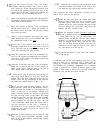
49
q
Check both conductors of the power cord to see
that they are tinned to secure every strand. Con-
nect one lead of the power cord to FC lug #2. (S).
50
0
Select another spade lug and connect it to the free
end of the power cord. (S).
59
0
Place the red, black and yellow wires toward the
left and twist them lightly together. Keep these
against the chassis and connect the red wire to dual
fuse clip FR lug #5. Connect the yellow wire to FR
lug #6. Connect the black wire to the center of the
bare wire between the two capacitors CL and CR.
(S). Six other wires will be connected to the center
of this bare wire. The amplifier will have the lowest
hum if the last wire to be connected (from the
transformer
-a heavy wire) is placed in the exact
center of this link between the two capacitors, so
leave a small space for it. However, all 7 wires
should be connected as near to the center point as
possible.
51
q
Prepare a 13” white wire. Connect one end to the
lower hole of
LT
lug #6. (S). Using the lower hole
will make it easier for other wires to be connected
to the same lug.
NOTE
FOR MULTIVOLTAGE
OPTION
:
This wire may need
to be 1” longer, and may connect to another termi-
nal for some line voltages.
60
c]
Prepare a 4 1/2” red wire and connect one end to
PC-9 eyelet #3. (S).
61
/-J
Prepare a 5-3/4” yellow wire and connect one end to
PC-9 eyelet #2. (S). Place this wire and the red wire
from eyelet 3 to the left.
Twist
them lightly together
and connect the red wire to RY lug #B. (S).
Con-
nect the yellow wire to RY lug #A. (S).
11