


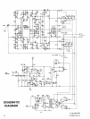
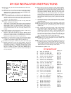
DH-502
INSTALLATION
INSTRUCTIONS
1.
3
2.
3
3.
cl
4.
El
5.
6.
0
7.
8.
c!
9.3
Disconnect AC power from the DH-500 and remove all connect-
ing
cables.
Remove the 17 screws which secure the cover along the top front,
sides and rear. Set cover aside. DO NOT GRAB THE AMPLI-
FIER PANEL OR HANDLES WHEN THE
COVER IS RE-
MOVED. You might bend the chassis.
Turn
the
amplifier over, or stand it on the nansformer end.
Loosen, but do not remove the two front screws which secure the
amplifier module near the front (center) of the chassis. Remove
the
two screws at the rear which secure the module.
Return
the
amplifier
to
its upright position.
Prepare one each red and green wires each 16” long. Twist them
together throughout their length.
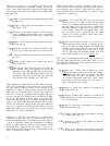
Select
the
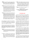
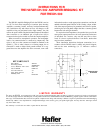
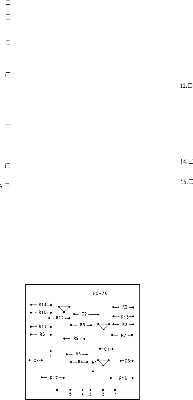
PC-7A circuit board. Note
that
the eyelets arcnumbered
on the circuit side of the board, with eyelet
#l
to the left when the
row
of eyelets
is nearest you, and the board is upside down to
make soldering easier. Connect the wires from the components
side of
he board,
and be sure each is securely soldered to the
circuitry.
Connect
the red
wire of the twisted pair to eyelet
#
1 of PC-7A. (S)
Connect
the
green wire to eyelet
#3.
(S)
Prepare a
3-l/2”
green wire and a 4” red wire. With one pair of
ends
even,
twist
these
together. At the
uneven
ends, connect the
green wire to cyelet
#4
of PC-7A. (S). Place the pair off toward
eyelet
#l,
and connect the red wire to eyelet
#6.
(S)
Prepare a 5”
red
wire and a 6” green wire. Twist these together
with
one pair of ends even. At the
even
ends connect the red wire
to
eyelet
#2.
(S) Connect the green wire to eyelet
#5.
(S)
Unsolder
the
twistcd pair of leads from eyelets 1 and2 of the right
amplifier module at the center rear of the amplifier. This pair of
leads which
connects
to the
right input socket, will no longer be
used
while the amplifier is funtioning monophonically. These
leads
must be
taped
securely so
that
there is no possibility for the
bare
wire
to contact any portion of the circuit. Masking tape is
sufficient, but electrical tape is preferred. These leads may be
removed
if desired.
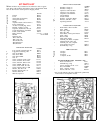
COMPONENT SIDE
PC-‘IA
c
Rl’
06
05
v
A
c
R2-0
c
RID-a
c
c2-
cR12-0
-
R13-
.--
Rll-
A
-
R5--r
v
-
R3-
c
R6-0
04
02
c
R9+
-
R7-
i
t-Cl_
)-
R6+
i
+c4-+
R15
A
D--R&
Rl
v
*C3+
1
03
J
01
-
R17-
-
R16--,
.
.
6
:
1
;
:
1
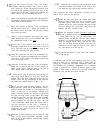
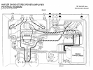
10. Remove the rear rop screw securing the right channel amplifier
circuit board
to
the hear sink
just
above where the twisted pair
was
disconnected. Do nor lose the fiber spacing washer which is
between the circuit board and the heat sink. This washer is not
used on later production
DH-500s.
Select one of
the
screws from
the bridging kit, and the mounting bracket. The bracket
is
anchored
at
this location, flat surface up, with the screw
inserted
fust through the single tab from inside the bracket. then
through
the circuit board. the fiber spacing washer, (optional) and
into
the
heat sink.
11. Select the two screws and nuts and the circuit board PC-7A. With
the components facing out, secure the board
to
the
outer surface
of the bracket tabs.
12.0
Select the short twisted pair of wires connected
to
eyelets 4 and
6. Connect the red wire
to
the upper eyelet
#l
of
the
right circuit
board at the center rear. (S) Connect the green wire
to
the lower
eyelet
#2.
(S)
13. Place
the
long pair of wires from
eyelets
1 and 3 down between
the amplifier module mounting bracket and the back of
the
chassis. The module can be tilted forward
to
facilitate this.
Connect
the
red wire
to
the lower
ey
elet
#l
on
the
left
circuit
board. (S)
The
easiest way is to wrap
it
in a tight loop around
the
bare stub of the wire presently connected to this eyelet. Be sure
both wires are soldered securely
to
he board. Connect
the
green
wire
to
the upper eyelet
#2
in the same fashion. (S)
14.0
Making sure that no wires are trapped by the mounting bracket,
reinstall
the.
two screws securing the rear of the module
to
the
chassis. Tighten all 4 screws.
15.0
Connect the red wire of
the
remaining twisted pair from PC-7A
to eyelet
#6
of the PC-9 circuit board behind
the
power
trans-
former,
(S)This
wire may be
connecred
to
the stub of the existing
wire as before. Connect the green wire to eyelet
#4
of PC-9. (S)
Eyelei
#I
of PC-9 is nearest the edge of the chassis.
16.0 Reinstall the amplifier cover.
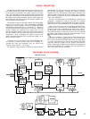
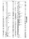
Rl
R2
R3
R4
R5
R6
R7
R8
R9
RlO
Rll
R12
R13
R14
R15
R16
R17
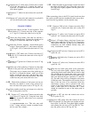
PC-7A PARTS
22.1K,
l%, metal film
2.2K.
1/4w,
5% carbon film
2.2K,
1/4w,
5% carbon film
47 ohms,
1/4w.
5% carbon film
47 ohms,
1/4w.
5% carbon film
8.2K,
1/4w,
5%,
carbon film
8.2K,
1/4w,
5%,
carbon film
47 ohms,
1/4w,
5% carbon film
47 ohms,
1/4w,
5% carbon film
2.2K,
1/4w,
5% carbon film
2.2K,
1/4w,
5% carbon film
22.1K,
l%, metal film
IO0
ohms,
1/4w,
5% carbon film
100 ohms,
1/4w,
5% carbon film
47 ohms,
1/4w,
5%
carbon film
3.3K,
lw,
5%
metal film
3.3K,
lw, 5%. metal film
RMP/4-2212
RC/4-222
RC/4
-222
RC/4-470
RC/4-470
RC/2-822
RC/2-822
RC/4-770
RC/4-770
RC/4-222
RC/4-222
RMP/4-2212
RC/4-101
RC/4-101
RC/4-770
RM l-332
RMl-332
Cl 1
OmF,
16V.
non-polarized
CERNP-106
c2
6.8pF.
1
00V,
dipped mica
CM
-068
c3 22mF.
25V,
electrolyte
CER-226AA
c4 22mF.
25V,
electrolyte
CER-226AA
Ql
BC55OC
NPN nansistor
SSH-650
Q2
BC55OC
NPN transistor
SSH-650
Q3
BC56OC
PNP transistor
SSH-65 1
Q4
BC56OC
PNP transistor
SSH-65 1
Q5
MPSA63 PNP transistor
SSH-695
Q6
MPSA13 NPN transistor
SSH-645
LIST
PC-7A PARTS LIST