


4. Allow the connection to cool undisturbed.
Remember that the connection is made by the solder,
not by mechanically attaching the wire to the terminal.
Usually the wire is looped through the lug and crimped in
place, but some prefer to just place it through the hole and
rely on the stiffness of the wire to hold it while soldering.
Eyelet connections, of course, are handled this way.
Good solder connections are essential for trouble-free,
noise-free operation.
A good
solder joint does not require
much solder around the conductors. Never “butter” par-
tially melted solder on the joint, as it is useless. A good
connection looks smooth and bright because the solder
flows into every crevice when the parts are hot enough.
The iron must have a bright, shiny tip to transfer heat eas-
ily to the junction. That’s why the damp sponge should be
used frequently to wipe the tip, and occasionally you must
add a small amount of solder to the tip, too. If a connection
is difficult to heat, “wet” the tip with a small blob of solder
to provide a bigger contact surface to the joint. Once the
solder flows around the conductors, any movement must
be avoided for a few
seconds
to allow a good bond. When
cool, check the connection by wiggling the wire. If in
doubt, or if the connection is not shiny, re-heat the joint.
Excess solder may be removed from a connection by heat-
ing it and allowing the solder to flow onto the iron, which is
then wiped on the sponge.
ALL SOLDER USED MUST BE ROSIN CORE
Never use acid core solder or any separate flux in elec-
tronic work. Silver solder is also not suitable. If in doubt
about unmarked solder, always obtain a fresh supply of
rosin core solder. We recommend
60/40
for easiest use. Do
not confuse it with 40160, which is harder to melt.
The general procedure is to use a hot iron for a short time
to heat a connection, then add solder with the iron still in
contact. Remove the solder once it flows, and then remove
the iron. A cooler iron applied for a longer time is more
likely to damage components, or lift the copper circuit pat-
tern from the boards. A break in the etched circuit can be
mended by simply soldering a small piece of wire across it.
D
O
not allow much build-up of solder on the tip of the iron,
or it may fall into adjacent circuitry.
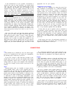
When soldering to an eyelet or hole on the board, insert
the wire from the components side, and apply the iron to
the bottom, leaving some bare wire exposed so that you
can see that the eyelet is then filled with solder for a secure
bond. A round wooden toothpick is suggested so that you
can heat and clear an eyelet of solder if it hinders your in-
serting the wire. Some builders prefer to clear every eyelet
first with a touch
of the
iron and toothpick. Others connect
the lead by bringing it up to the center of the eyelet on top
of the board, applying the iron from the bottom of the
board, and pushing the lead in as the solder in the eyelet
melts. If the wire has first been “tinned,” usually no addi-
tional solder is necessary, but it is a good practice to push
the wire through, and then back it up a bit, to be sure solder
fills the eyelet. On the bottom of the board, make certain a
bright, shiny flow is evident from the wire onto the circuit
pattern on the board.
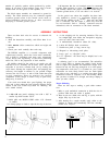
"Tinn
ning”
refers to the process of applyinga light
coat-
ing ofsolder to the bared wire end. This keeps all the
strands secured, and also makes a good connection easier.
Simply touch the wire with the iron for a couple seconds,
and apply solder. Allow the excess to flow away onto the
iron. When properly done, the wire is uniformly bright,
and no larger than before. The hookup wire supplied with
this kit does not normally need tinning, for it is pre-tinned.
Wiring the Kit
If any components are unfamiliar to you, checking the
pictorial diagram should quickly identify them. Or, the
quantities, and the process of elimination as you check the
parts list, will help. The pictorial diagram is necessarily
distorted to some extent for clarity, so that you can trace
every wire in a single overall view for verification as you
work. You may wish to check off on the diagram as you
solder each location.
To
“prepare” a wire means to cut the designated length
from the coil of that color, and strip about
l/4”
of insulation
from each
end. The
wire supplied in the kit is #18 and
#22,
so you can set adjustable wire-strippers accordingly. The
transformer leads are
#18,
and the line cord is
#16.
Be
careful that you do not nick the wire when you strip
it (that
can happen more easily if you do not use wire strippers) for
that weakens it. The wire supplied in this kit is “bonded
stranded,” which provides exceptional flexibility with re-
sistance to breakage for easier use.
Whenever a connection is to be soldered, the instruc-
tions will so state, or indicate by the symbol (S). If more
than one wire is to be soldered to the same point, they will
be indicated by (S-2), (S-4), etc. If soldering is not called
for, other connections have yet to be made to that termi-
nal. They would be more difficult if the connection was al-
ready soldered. Every connection in the kit will be sol-
dered when it is complete. After soldering a connection, it
is best to clip off any excess lead length to minimize the
possibility of a short circuit (as on switch lugs, where ter-
minals are very close together), and for neatness.
Be sure that uninsulated wires ca
terminals or the chassis metalwork.
nnott
touch adjacent
The symbol
(#)
indicates a connection is to be made to
that point. When a lug number is specified without
(#),
it is
simply a locating reference.
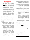
When the instructions call for twisting two or three
wires together, the length of wire indicated anticipates a
fairly tight, uniform twist by hand, of three full turns every
two inches. If you find the wires too short, loosening the
twist will gain some needed length.
Handle
the
circuit boards carefully. They represent a
major part of the kit cost. Stand-up components,
such as
transistors, should be checked when you install the
mod-
ule, to be sure all leads are separated, and that the large
electrolytic capacitors have not broken loose from the
board.
Take the time to be accurate and neat, and you can be
sure that your completed amplifier will meet the per-
formance of a factory assembled unit, and can continue to
perform properly for years to come. Check your work, and
make sure the entire step has been completed before plac-
ing a check mark in the space provided, and continuing on
to the next step.