MECHANICAL ASSEMBLY
1
0
For security in shipping, the power transformer
and the amplifier module have been fastened to the
chassis. Remove the chassis cover, the inner front
panel and the larger front plate, and set these aside.
Be particularly careful in handling the amplifier
module. to see that the leads of the
upright
compo-
nents on the circuit boards are not stressed.
This
module accounts for more than half the kit cost,
and has already been thoroughly tested for
specified performance before it was packed.
Turn the chassis upside down, and rest it on the
module and transformer to remove these parts. In-
clude all of the hardware you have removed with
the rest when you check off the components
against the parts list in the back of this manual. We
recommend this check-off to be sure you have ev-
erything, and to enable you to identify any unfamil-
iar items by comparing them with the pictorial
diagram. Although the perspective of the diagram
has sometimes been distorted to show connections
more clearly, it should enable you to recognize any
unfamiliar component. An egg carton is ideal for
keeping small items like hardware at hand.
It will simplify matters if you first separate the
#4
nuts
from the
#6
nuts, which have the same outside dimen-
sions. A
#4
screw will pass through a
#6
nut, aiding iden-
tification.
A
“set”
of hardware includes one screw and one KEP nut
(with its attached lockwasher). Always install the
lockwasher side of the nut first. If the size of the hardware
is not specified, use the
#4
size, which is the smallest.
#10
is the largest. Always insert the screw from the outside of
the chassis.
2
0
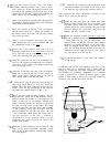
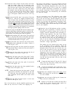
With the chassis upside down, select the 4 rubber
feet and 4 sheet metal screws. The screw head re-
cesses fully into the foot. Install these in the holes
which are about I” in from each corner.
3
0
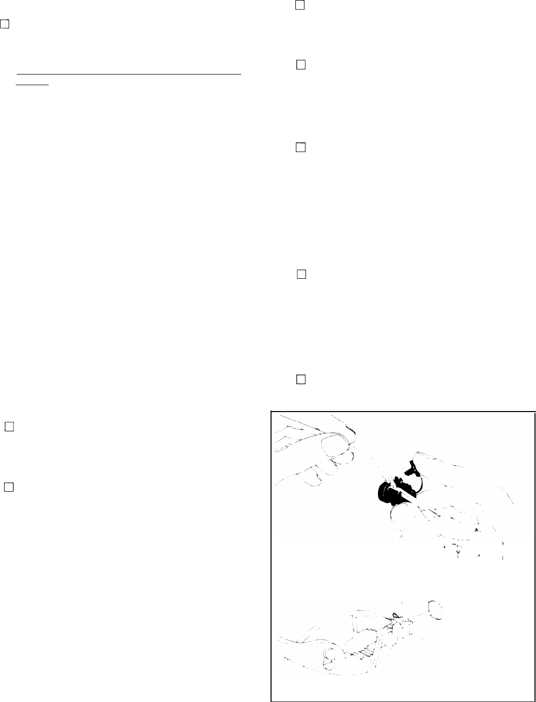
Select the AC line cord and the plastic strain relief.
Separate the two conductors of the cord for 2 in-
ches. Strip
l/4”
of insulation from each lead. Twist
the bare strands tightly, and tin each lead. 13” from
the ends make a sharp “V” in the cord by bending it
sharply back on itself. Install the strain relief as
shown, with the small end of the strain relief
nearest the stripped end of the line cord. Crimp the
two halves of the strain relief around the wire at the
V with heavy pliers, to partially form it before in-
sertion into the back panel. Considerable squeez-
ing is necessary, because the thick insulation “pops
back” quickly. Then grip the larger diameter of the
strain relief with the tips of heavy pliers, squeeze it
tightly, and insert the end of the cord through the
back panel AC hole from the outside. Note that the
hole has two flat sides, and the relief is shaped ac-
cordingly. This is a very tight
fit-you
will have to
pull on the cord to help-but it snaps into position
when fully inserted.
4
0
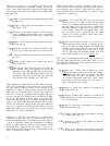
Select the two input sockets and 4 sets of hardware.
Install the sockets at LS and RS inside the chassis
so that the short lug is nearest the hole in the chas-
sis between the two sockets.
5
0
Select the single ground lug (with lockwasher
teeth) and one set of hardware. Install it between
the input sockets. Point it toward the bottom, and
bend it out for access. Be certain this lug is tight.
The locking teeth must cut through the chassis
paint for a good ground connection.
6
0
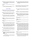
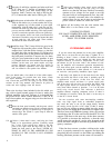
Select the two round fuse holders with caps, and
their
l/2”
hardware: rubber washers, metal
lockwashers, and nuts. First install the rubber
washer on each holder, so it will be outside the
chassis, and then fasten them at locations LF and
RE The holes have flats which mate with the fuse
holder to keep it from turning. Point the tip lugs to-
wards each other. Be sure all of this hardware is
tight, as it will not be accessible once the amplifier
is completed.
7
17
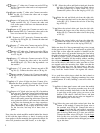
Select the two red output terminals and their
hardware: the red washers, 4 nuts without
lockwashers, and two plain connecting lugs. Note
that each part of the terminal has a flat which mates
with the flat top of the chassis hole. Install the ter-
minals in the two center holes LR and RR so that
the washer flat is engaged, tighten one nut securely,
add the lug pointing up, and tighten the second nut.
8
0
Select the two black output terminals, their hard-
ware, and two plain connecting lugs. Install them at
LB and RB as in the previous step.
-
.
.
,
T
F
.
I


