


62
0
Prepare a 3” white wire. Connect one end to RY lug
#4.
(S).
Connect the other end to red output termi-
nal LR. (S).
63
[7
Prepare another 3” white wire. Connect one end to
RY lug #6. (S). Connect the other end to output
terminal RR. (S).
64
0
Prepare a 16”green wire. Connect one end to black
output terminal LB. (S). Connect the other end
close to the center of the bare wire between the two
capacitors. (S).
65
0
Prepare an 18” green wire. Connect one end to out-
put terminal RB. (S). Connect the other end to the
bare wire between the two capacitors. (S).
66
q
Prepare an 11-E” green wire. Connect one end to
dual fuse clip FL lug #4. (S). Connect the other end
to CR lug #4.
67
0
Prepare a 7” white wire. Connect one end to FL lug
#3. (S). Connect the other end to CL lug
#l.
68
0
Prepare a 12”white wire. Connect one end to FR lug
#7. (S). Place this against the chassis and connect
it to CL lug
#l.
69
0
Prepare a 13” white wire. Connect one end to CL lug
#l.
(S-3). Connect the other end to the
rectfier
block DB lug #2. (S). This is the lug marked + on
the rectifier.
70
0
Prepare a
7 1/2’
green wire. Connect one end to FR
lug #8. (S). Connect the other end to CR lug #4.
71
0
Prepare another 8”green wire. Connect one end to
CR lug #4. (S-3), Connect the other end to DB lug
#3.
(S).
72
0
Strip a
3/4"
piece of light wire bare. Connect it be-
tween the short ground lug of input socket LS and
the separate ground lug between the 2 input soc-
kets.
73
0
Prepare a 14” black wire, but strip
3/4"
of insulation
from one end. Thread the longer bared end through
the separate ground lug, and connect it to the short
ground lug of input socket RS. Solder only the two
wires at the center ground lug at this time. Place the
wire against the chassis, and connect the other end
to the bare wire between the two large capacitors.
(S). This is the 4th of 7 wires connected at this
point. Remember to leave space in the exact center
for the last wire, but keep all of these close to-
gether.
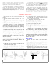
Now place the wired amplifier module behind the chassis
in line with the input sockets, so that it is resting on the
foam gasket, with the mounting feet against the chassis. Its
wires will protrude toward the chassis, or to the right.
74
q
Select the yellow and black twisted pair from the
left side of the module. Connect the black wire to
the short ground lug of input socket LS. (S-2).
Connect the yellow wire to the long lug of LS. (S).
75
0
Select the red and black pair from the right side,
and connect the black wire to the short lug of input
socket RS. (S-2). Connect the red wire to the long
lug of RS. (S).
76
0
Select the twisted white pair from the left side.
Connect the longer wire to the side lug of the fuse
holder LE (S). Connect the other wire to the tip lug
of
LF.
(S).
77
0
Select the twisted white pair from the right side.
Connect the longer wire to the side lug of RF (S).
Connect the other wire to the tip lug of
RF
(S).
Make sure that all of the unconnected long wires (except
for the green wires to eyelet 7 on each board) are placed off
to the right so that when the module is installed on the
chassis these wires will protrude between the feet below
the right circuit board. The wires to the #7 eyelets, as well
as those to eyelets 3 and 10, connect towards the front of
the amplifier. Carefully lift the module without touching
the components on the circuit boards. Swing it into posi-
tion on the chassis, and check to make sure that no wires
are trapped under the mounting feet. Make sure that the
input socket long lugs have not been bent so that any
shorts are possible there-or to the chassis. Keep all wires
away from the ‘inrush limiter’ disc-against the chassis.
It is a good idea at this time to check the fan by hand, to
make sure it rotates freely. Shipping sometimes may cause
a misalignment. If it rubs, bending a strut will correct the
problem.
78
0
Select 4 sheet metal screws and secure the module
to the chassis. The easiest procedure may be to tilt
the whole assembly backwards so that the module
is again lying on the gasket, giving you access to the
bottom of the chassis. Start the screws, and then
check again to make sure no wires are trapped be-
fore tightening the screws fully.
79
0
Select the green and white twisted pair from the
bottom of the module. Connect the green wire to
the terminal strip
LT
lug
#l.
Connect this wire to
the lower hole in that lug, and solder it separately
from the two wires which are soldered to the upper
part of the lug, Make sure all 3 wires are soldered.
Connect the white wire to
LT
lug #4. Use the lower
hole for this wire, and solder it separately now. Do
not solder the capacitor lead to the upper part of the
lug at this time.
12