


80
0
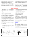
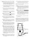
Select the triad of black, red and yellow wires from
under the module. These will be connected to the
right end of the terminal strip, and to prevent the
heat from the large resistors from melting the insu-
lation on the wires, connect the wires from behind
the terminal strip and keep them against the chas-
sis, so the resistors will be above them. Connect
the black wire to
LT
lug
#5.
Connect the yellow
wire to
LT
lug
#6.
Connect the red wire to LT lug
#7.
81
0
Select one of the
300*
ohm 7 watt resistors. Trim each
lead to
3/4’
’
.
Strip two
1/Z”
lengths of insulation from a
piece of heavy wire, and place one piece over each
resistor lead as insulation. Connect one lead to LT lug
#5
on the front side of the strip. Connect the other lead
to lug
#6.
Because lug
#6
will eventually have several
wires, it is important that each wire be placed as low as
possible in the opening, and crimped so as to maintain
the largest possible opening for the last wire.
*
In these two steps, use the 600 ohm resistors instead, if the
overseas multivoltage transformer option is wired for
200
-
240 volt AC lines. See page 18. A 220 volt fan must be used,
part
#AAI28,
and will have been fitted if specified.
82
0
Select the remaining
300”
ohm resistor. Trim each lead
to
3/4"
and place this resistor on the back side of the
terminal strip and connect one lead to LT lug
#5.
(S-3).
Connect the other lead to LT lug
#7.
(S-2).
83
0
Select the white wire from the left circuit board,
protruding from underneath the module. Connect it
to RY lug
#7.
(S-2).
84
0
Select the long white wire from
eyelet
5 on the right
circuit board. Place it under the relay and connect it
to RY lug
#9.
(S-2).
85
0
Connect the short white wire from the
left
side of
the module to fuse clip FL lug
#l.
(S).
86
0
Connect the longer green wire from
eyelet 7 on
the
left side to the bare wire between the 2 large
capacitors. (S). Place it down against the chassis.
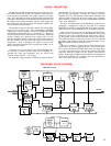
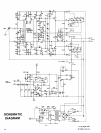
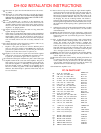
The wiring of the amplifier is now to be completed with the
installation of the power transformer and two disc
capacitors. The following instructions refer to the 120 volt
transformer supplied for the USA. If your kit is supplied
with the optional multivoltage transformer for overseas
use, separate instructions in this manual will diagram,
both in pictorial form, and schematically, the connection
for each line voltage.
NOTE FOR MULTIVOLTAGE OPTION
:
The following steps which
describe the installation of the capacitors, and the connec-
tion of the two red leads, and the red/yellow lead of the
transformer are to be followed for all units. Only the con-
nections for the black and black/white transformer leads,
and the additional leads supplied on your transformer, may
differ. You should follow all the other steps to the comple-
tion of your amplifier.
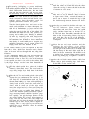
91
0
Select the 4 sets of #10 hardware and the 4 washers,
and the power transformer. Carefully place the
transformer in position, making sure no wires are
trapped, with the transformer leads protruding to-
ward the large capacitors. You may if you choose
shorten any lead for neatness, but be sure you do
not cut any lead too short, as leads which are cut
too short for re-use may void the transformer war-
ranty. If you are using the multivoltage transformer,
be sure you leave leads long enough for possible
alternative voltage applications.
The washers are to be placed on the screws on top
of the transformer feet for stiffening. Install the
bolts near the edge of the chassis first. That will
determine which of the inner sets of holes are to be
used. It may be easiest for you to tilt the assembly
up on its right side, so the transformer weight is
supported by the work surface, or you can turn it
upside down. Be careful the transformer does not
swing into the circuit board on the module! Before
you tighten any of the mounting bolts, check to be
sure the line cord and other wires are clear of the
transformer feet.
87
0
Connect the green wire from eyelet
10
on the left
side to FL lug
#2.
(S).
92
q
Connect the black lead to LT lug
#4.
(S-3). One of
these wires has most likely already been soldered
to the lower hole of this lug.
88
0
Connect the short green wire from
eyelet
10 on the
right side to FR lug
#6.
(S-2).
93
q
Connect the black/white lead to
LT
lug
#6.
(S-4).
One wire has most likely been soldered to the lower
hole of this lug.
89
q
Connect the long green wire from eyelet 7 on the
right board to the bare wire between CL and CR.
(S). Place this wire down against the chassis. One
more connection will be made at the center of this
bare wire.
94
0
Connect the red/yellow lead to the center of the
bare wire between CL and CR. Be sure all 7 wires
are well soldered.
90
0
Connect the white wire from eyelet 3 on the same
board to FR lug
#5.
(S-2).
95
0
Connect one red lead to DB lug
#l.
Connect the
other red lead to DB lug
#4.
Now is the best time to turn the amplifier upside down and
shake out any loose bits of solder, wire clippings, etc.
96
q
Prepare a 13-1/2”r ed wire. Connect one end to PC-9
eyelet
#l.
(S). Place this wire down against the
chassis and connect it to DB lug
#l.
13