


DVI 201 Tx/Rx • Installation and Operation
Installation and Operation, cont’d
2-28
DVI 201 Tx/Rx • Installation and Operation
2-29
INPUT
Rx
Tx
RS-232
PASS THRU
DVI
AUDIO L+R
1
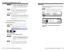
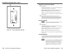
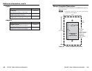
DVI 201 A D Tx Transmitter Front Panel
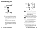
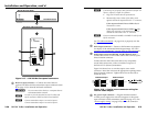
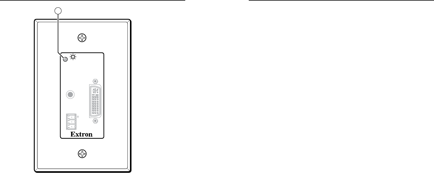
Figure 2-27 — Decora model power indicator
Transmitter control and indicator
a
PowerLED—
DVI201Tx(non-Decora)—This front panel LED lights green
to indicate that the unit is receiving power:
DVI201ADTx(Decora)—This two-color front panel LED
lights to indicate signal and power status as follows:
Amber—The unit is receiving power but not a DVI input.
Green— The unit is receiving power and a signal is present on
the DVI input.
b
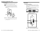
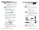
DDCRouteswitch(DVI201Tx([non-Decora]only)—
This rear panel switch selects either the remote or local DVI
display as the route of the display resolution data (the display
data channel [DDC]) and HDCP copyright decoding keys.
Receiver indicator
N
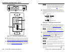
Both receiver models have power indicators in the same
location as on the related transmitter model.
a
PowerLED—
DVI201Rx(non-Decora)—This front panel LED lights green
to indicate that the unit is receiving power:
DVI201ADRx(Decora)—This two-color front panel LED
lights to indicate signal and power status as follows:
Amber—The unit is receiving power but not a TP input.
Green— The unit is receiving power and a signal is present on
the TP input.
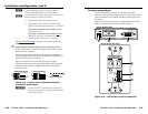
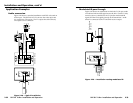
System operation
After the transmitter, the receiver, and their connected devices
are powered up, the system is fully operational. If any problems
are encountered, ensure all cables are routed and connected
properly.
N
Ensurethatthevideosourceanddisplayselectedforthe
DDCareproperlyconnectedtothetransmitter/receiver
pair, and that the transmitter, the receiver, and the
displayhavepowerappliedbeforepowerisappliedto
the video source. If all other devices are not turned on
beforethevideosource,theimagemaynotappear.