


DVI 201 Tx/Rx • Installation and Operation
Installation and Operation, cont’d
2-26
DVI 201 Tx/Rx • Installation and Operation
2-27
C
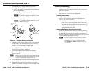
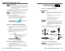
The length of the exposed (stripped) copper wires
is important. The ideal length is 3/16" (5 mm).
Longer bare wires can short together. Shorter wires
are not as secure in the connector and could be
pulled out.
N
Donottinthepowersupplyleadsbeforeinstallingin
the connector. Tinned wires are not as secure in the
connector and could be pulled out of the connector.
Use the supplied tie-wrap to strap the power cord to the
extended tail of the connector.
N
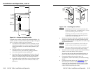
Yourtransmitter/receiverpairmayhaveshippedwitha
blue captive screw connector. This blue connector can be
plugged into either a blue or an orange power receptacle.
The blue connector does not have the extended tail or the
included tie-wrap.
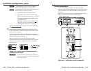
Snap the provided ferrite bead onto the DC power cable,
between the power supply and the DVI unit’s connector.
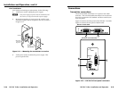
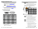
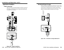
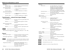
RS-232 connector wiring
Figure 2-25 shows how to wire the RS-232 connector for serial
communications.
N
TheRS-232connectorcanalsotransmitone-way
modulated infrared (IR) signals. See "Modulated IR
pass through"
on page 2-33.
Ground
Receive
Transmit
Connected RS-232
Device Pins
Tx/Rx
Pins
Rx
Tx
Figure 2-25 — RS-232 connector wiring
C
The length of the exposed (stripped) copper wires
is important. The ideal length is 3/16" (5 mm).
Longer bare wires can short together. Shorter wires
are not as secure in the connector and could be
pulled out.
N
Donottinthepowersupplyleadsbeforeinstallingin
the connector. Tinned wires are not as secure in the
connectors and could be pulled out of the connector.
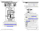
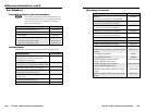
Operation
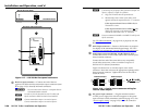
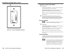
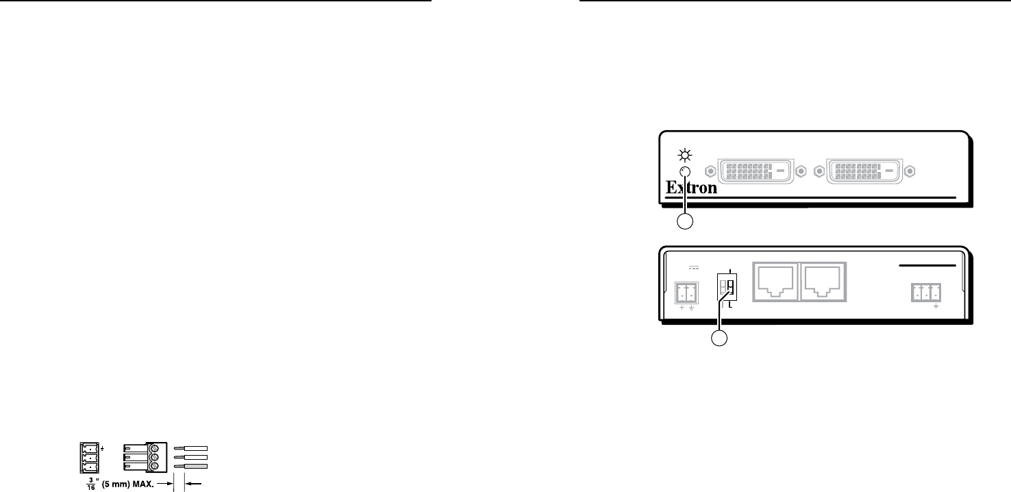
Figure 2-26 shows the DDC control and power indicator on the
non-Decora transmitter. Figure 2-27 shows the power indicator
on the Decora transmitter.
N
Both receiver models have power indicators in the same
location as on the related transmitter model.
DVI 200 Tx SERIES
DVI INPUT LOCAL OUTPUT
POWER
12V
0.4A MAX
DVI 201 Tx
RS-232
PA SS THRU
Tx Rx
DDC ROUTE
12
REMOTE
SPARE LOCAL
2
1
DVI 201 Tx Transmitter Rear Panel
DVI 201 Tx Transmitter Front Panel
Figure 2-26 — Non-Decora model control and
indicator