


DVI 201 Tx/Rx • Installation and Operation
Installation and Operation, cont’d
2-18
DVI 201 Tx/Rx • Installation and Operation
2-19
N
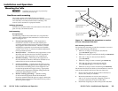
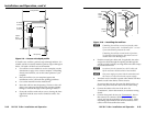
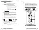
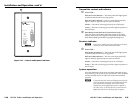
Connect transmitter output 1 to receiver input 1.
Connect transmitter output 2 to receiver input 2.
N
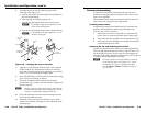
Ifnecessary,testforpropercableconnection(output1to
input 1, output 2 to input 2) as follows:
1. Plug both TP cables into the powered unit.
2. Momentarilyconnecteitherofthecablesonthe
opposite end into the unpowered unit‘s “2” connector.
If the unpowered unit’s Power LED is lit, the
connection is correct.
If the unpowered unit’s Power LED is not lit,
unplug the connector on the unpowered end and
connect the other cable to the “2” connector.
See "TP cable termination," on page 2-23, to properly wire the
RJ-45 connectors.
g
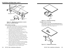
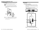
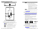
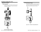
AudioOutputconnector(DVI201ADTx[Decora]only)—
Connect one end of a 5-wire audio cable to this 3.5 mm, 5-pole
direct insertion connector.
Connect the free end of the same cable from the transmitter to
any compatibly wired unit, such as a switcher, an amplier, or a
DVI 201 A D Rx (Decora) receiver.
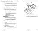
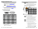
Figure 2-15 shows how to wire the captive screw audio
connector. Insert the wires into the appropriate openings in the
direct insertion connector. Tighten the screws on the side to
fasten the wires.
Unbalanced Output Balanced Output
Do not tin the wires!
L
AUDIO
OUTPUT
R
Tip
Sleeve (s) Sleeve (s)
Tip
NO GROUND HERE.
NO GROUND HERE.
Tip
Tip
Ring
Ring
L
AUDIO
OUTPUT
R
Figure 2-15 — Captive screw connector wiring for
transmitter audio output
C
Connect the sleeve to ground (Gnd). Connecting
the sleeve to a negative (–) terminal will damage the
audio output circuits.
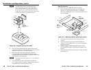
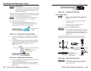
Receiver connections
The rack-mountable receiver is in a quarter rack width
enclosure. The wall-mountable receiver is in an enclosure that
can be mounted in UL standard wall boxes with Decora-style
face plates.
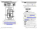
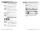
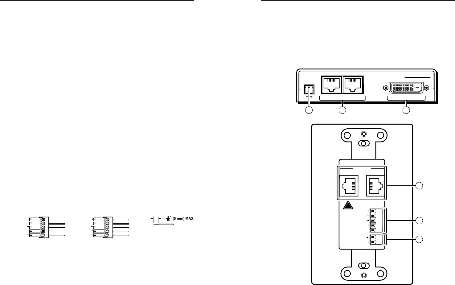
Figure 2-16 shows the rear panel of both DVI 201 Rx models.
Figure 2-17 shows the front panel of both models.
POWER
12V
0.4A MAX
DO NOT
CONNECT
TO LAN
12
INPUTS
DVI 201 A D Rx
L
AUDIO
INPUT
R
POWER
12V
0.4A MAX
DVI 201 Rx
12
DVI OUTPUT
DVI 201 Rx Rear Panel
11
10
DVI 201 A D Rx Rear Panel
8
11 8 9
Figure 2-16 — DVI 201 Rx rear panel connectors