


DVI 201 Tx/Rx • Installation and Operation
Installation and Operation, cont’d
2-12
DVI 201 Tx/Rx • Installation and Operation
2-13
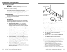
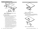
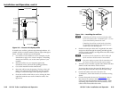
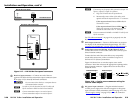
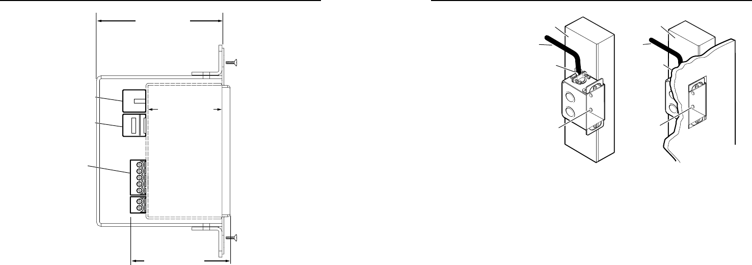
2.50” [63.5mm]
1.51” [38.48mm]
1.85” [47mm]
Junction Box
TP Cable
(no boot)
TP Cable
(no boot)
Captive
Screw
Connectors
Figure 2-9 — Decora unit depth profile
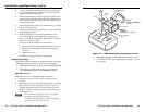
To install a new wall box, perform steps 1 through 9 below. If a
suitable wall box is already installed, perform steps 6 through 9
below. UL listed wall boxes are recommended.
1. If a wall box is not available to use for a template, use the
dimensions on page A-9 to create a template. If installing
directly into furniture, cut out the center portion of your
template.
2. Place the wall box (or your template) against the
installation surface, and mark the opening guidelines.
3. Cut out the material from the marked area.
4. Insert the wall box into the opening. The box or the wall
plate’s rear connectors should t easily into the opening.
Enlarge or smooth the edges of the opening if needed.
5. Secure the wall box with nails or screws, leaving the front
edge ush with the outer wall or furniture surface. See
gure 2-10.
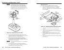
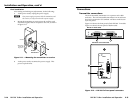
Signal
Output
Cable
Cable
Clamp
Wall Stud
Screws
or Nails
Wall Stud
Cable
Clamp
Screws
or Nails
Signal
Output
Cable
Figure 2-10 — Installing the wall box
N
If attaching the wall box to wood, use four #8 or #10
screwsor10-pennynails.Aminimumof0.5"(1.3cm)
of screw thread must penetrate the wood.
If attaching the wall box to metal studs or furniture,
use four #8 or #10 self-tapping sheet metal screws or
machine bolts with matching nuts.
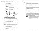
6
. Feed the twisted pair cables and, if applicable, the audio
and power cables through the opening and through the
wall box punch-out holes, securing them with cable clamps
to provide strain relief.
N
In order to fit in the junction box, the TP cables and
RJ-45 connectors should not have a boot installed.
N
Onepowersupplycanpowerboththetransmitterand
thereceiver,soonlyoneunitneedsapowersupply.
7. Trim back and/or insulate exposed cable shields with heat
shrink to reduce the chance of short circuits.
To prevent short circuits, the outer foil shield can be cut
back to the point where the cable exits the cable clamp.
8. Connect the cables to the rear of the unit. See
"Connections", later in this manual, for connector wiring
details.
9. Connect front panel devices (see "Connections", later in
this manual, for connector details), restore the power
supply, and test the transmitter/receiver system. Make
any cabling adjustments before nal installation, as the
cables will be inaccessible afterwards.