


DVI 201 Tx/Rx • Installation and Operation
Installation and Operation, cont’d
2-16
DVI 201 Tx/Rx • Installation and Operation
2-17
POWER
12V
0.4A MAX
DVI 201 Tx
RS-232
PA SS THRU
Tx Rx
DDC ROUTE
1 2
REMOTE
SPARE LOCAL
POWER
12V
0.4A MAX
L
AUDIO
OUTPUT
R
DO NOT
CONNECT
TO LAN
1
2
DVI 201
A D Tx
O
U
T
P
U
T
S
5 6 4
7
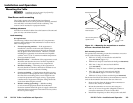
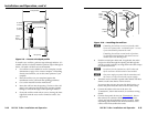
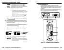
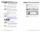
DVI 201 Tx Rear Panel
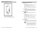
DVI 201 A D Tx Rear Panel
6
5
Figure 2-13 — DVI 201 Tx rear panel connectors
a
DVIinputconnector —Connect a DVI cable between this port
and the DVI output port of the digital video source. See "DVI
connector pin assignments,"
on page 2-22, for pin assignments.
b
Localoutput(DVI201Tx([non-Decora]only)— If desired,
connect a DVI monitor for local monitoring of the input digital
image. See "DVI connector pin assignments," on page 2-22, for
pin assignments.
N
Inasystemwherethelocaloutputisnotused,ensure
thatyoupoweruptheenddisplayrstbeforethevideo
source. Route the DDC to the remote end (see the
DDC Route DIP switch [item
b
, in "Operation", on
page 2-29]).
c
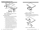
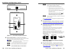
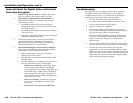
Audioinput(DVI201ADTx[Decora]only)—Connect an
unbalanced stereo audio source to this 3.5 mm mini stereo jack
for unbalanced audio input. Figure 2-14 shows how to wire the
audio plug.
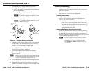
Tip (L+) Sleeve (Gnd)
Tip (L+)
Ring (R+)
Sleeve (Gnd)
Figure 2-14 — Audio input connector wiring
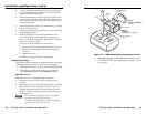
d
RS-232connector—Connect a serial communications port to
this 3.5 mm, 3-pole captive screw connector for bidirectional
RS-232 communication. See "RS-232 connector wiring," on
page 2-26, to wire the connector.
N
TheRS-232connectorcanalsotransmitone-way
modulated infrared (IR) signals. See "Modulated IR
pass through"
on page 2-33.
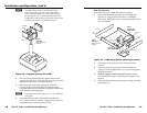
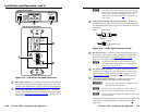
e
DCpowerinputconnector—Plug the included external
12 VDC power supply into either this connector or the power
input connector on the receiver (item
k
on page 2-21). See
"Power supply wiring," on page 2-25, to wire the connector.
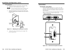
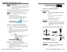
f
Transmitteroutputconnector—Connect one end of two
separate TP cables to these RJ-45 female connectors.
C
Do not connect these devices to a computer data or
telecommunications network.
N
In order to fit in the junction box, the TP cables and
RJ-45 connectors should not have a boot installed.
N
Extron recommends 28AWG to 24AWG TP cable for the
RJ-45 connectors.
Connect the free ends of the same TP cables from the transmitter
to the receiver’s Input RJ-45 female connectors (item
h
on
page 2-20).