


DVI 201 Tx/Rx • Installation and Operation
Installation and Operation, cont’d
2-14
DVI 201 Tx/Rx • Installation and Operation
2-15
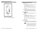
Final installation
After testing and making any adjustments, do the following:
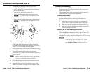
1. At the power outlet, unplug the power supply.
N
Onepowersupplycanpowerboththetransmitterand
thereceiver,soonlyoneunitneedsapowersupply.
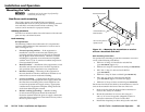
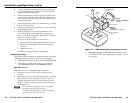
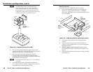
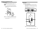
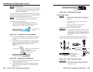
2. Mount the transmitter or receiver into the wall box, and
attach the supplied Decora faceplate to the unit, as shown
in figure 2-11.
Wall opening
is flush with
edge of box.
Wall Box
Decora
Faceplate
Extron
DVI 201 A D
D
VI
A
U
D
IO
IN
INPU
T
Tx
Rx
RS-232
PAS
S TH
RU
Figure 2-11 — Mounting the transmitter or receiver
3. At the power outlet, reconnect the power supply. This
powers up both units.
Connections
Transmitter connections
The rack-mountable transmitter is in a quarter rack width
enclosure. The wall-mountable transmitter is in an enclosure
that can be mounted in UL standard wall boxes with Decora-
style face plates.
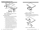
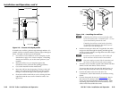
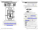
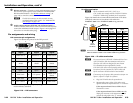
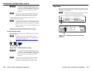
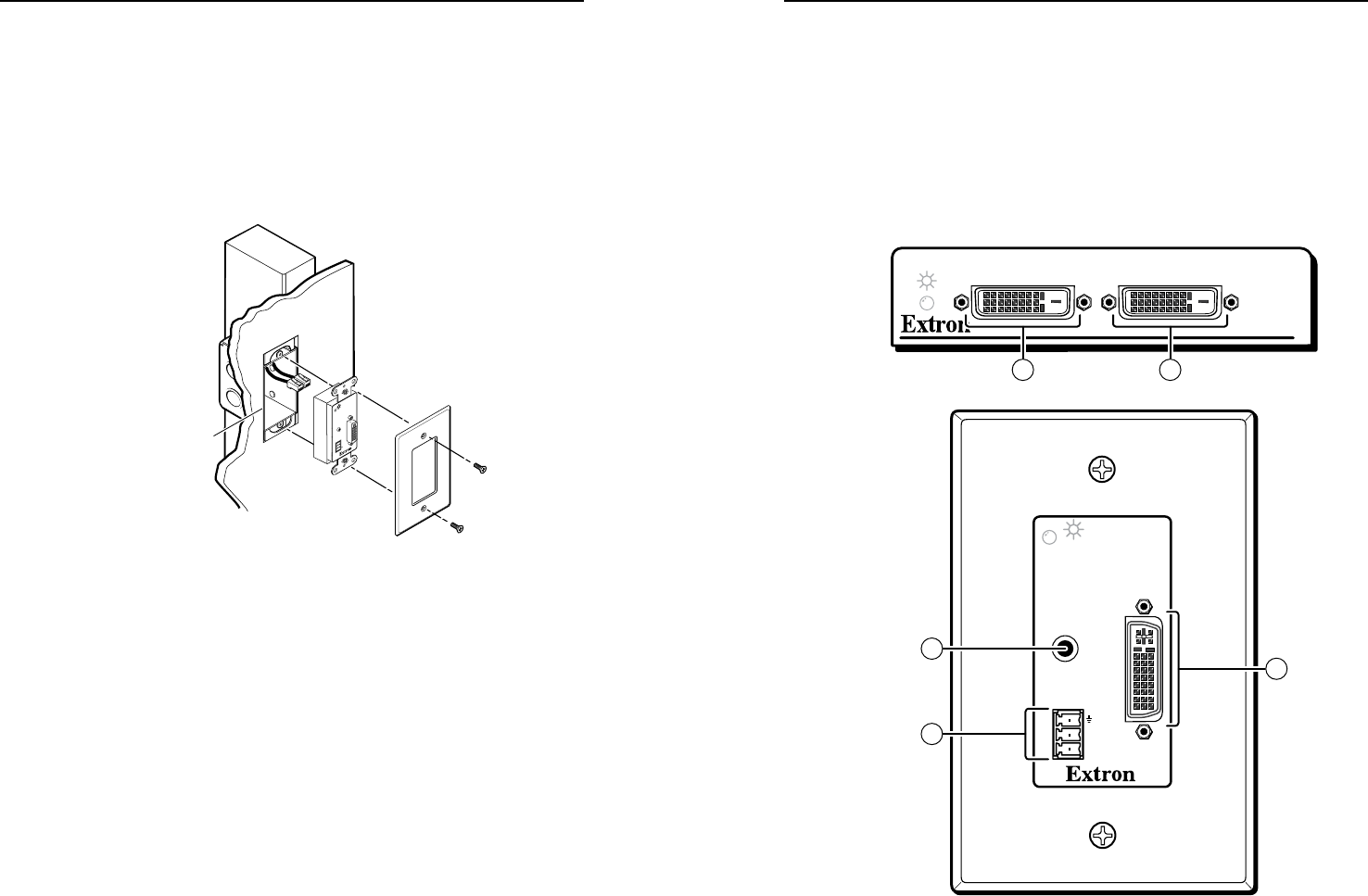
Figure 2-12 shows the front panel of both DVI 201 Tx models.
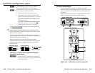
Figure 2-13 shows the rear panel of both models.
DVI 200 Tx Series
DVI INPUT LOCAL OUTPUT
DVI 201 Tx Front Panel
DVI 201 A D Tx Front Panel
INPUT
Rx
Tx
RS-232
PASS THRU
DVI
AUDIO L+R
4
21
1
3
Figure 2-12 — DVI 201 Tx front panel connectors