


DVI 201 Tx/Rx • Installation and Operation
Installation and Operation, cont’d
2-24
DVI 201 Tx/Rx • Installation and Operation
2-25
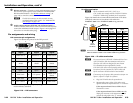
Terminating shielded cable
N
The transmitter and receiver pair works with unshielded
twisted pair (UTP) or shielded twisted pair (STP) cables;
but, to ensure FCC Class A and CE compliance, STP
cables are recommended.
The Tx/Rx includes four shielded RJ-45 connectors and a length
of self-adhesive shielded tape that you can use to make the STP
cables that connect the transmitter and receiver.
N
Extron supplies the connectors and the shielded tape.
YoumustsupplytheCAT5,5e,or6STPcable.
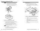
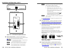
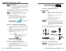
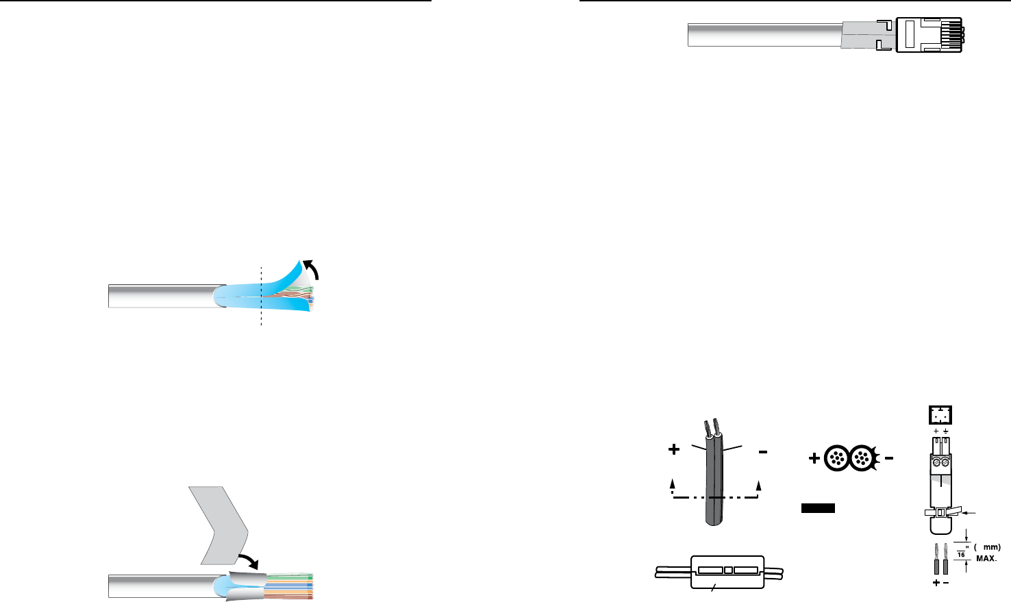
Terminate the STP cable as follows:
1. Peel back the cable shielding (gure 2-21) from the
end of the cable the length of the RJ-45 connector body
(approximately 7/8" [2.2 cm]) and fold it back.
Peel back shield and
fold back.
Figure 2-21 — Peeling back the cable shielding
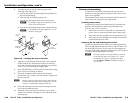
2. Cut away and discard the clear cellophane inner wrapper
from the end of the cable back to the folded-over cable
shielding.
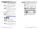
3. Peel the backing off the self-adhesive shielded aluminum
tape and wrap it around the folded-over cable shielding,
slightlyoverlapping the beginning of the tape
(gure 2-22).
Aluminum Ta pe
Wrap tape around folded foil shielding.
Slightly overlap.
Cut and save the excess tape
for other connectors.
Figure 2-22 — Wrapping the shielded tape
4. Cut the unused portion of the shielded tape and retain for
shielding other RJ-45 connectors.
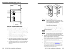
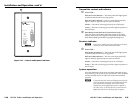
5. Crimp the RJ-45 cable in the normal manner, folding the
tangs at the end of the connector over the shielded tape
(gure 2-23).
Crimped Connector
Figure 2-23 — Crimped RJ-45 connector
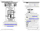
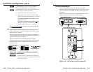
Power supply wiring
N
• Onlyonepowersupplyisrequired.Asinglepower
supplyconnectedtoeitherunitinthepairpowers
both units.
• Asinglepowersupplyisincludedwithsystems
packaged as a pair.
• Apowersupplyisalsoincludedwitheach
individually-packagedtransmitter.
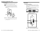
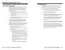
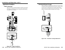
Figure 2-24 shows how to wire the connector.
C
Powersupplyvoltagepolarityiscritical.Incorrect
voltagepolaritycandamagethepowersupplyand
thetransmitterorreceiver.Identifythepowercord
negativeleadbytheridgesonthesideofthecord
(figure 2-24).
To verify the polarity before connection, plug in the power
supply with no load and check the output with a voltmeter.
Power Supply
Output Cord
SECTION A–A
Ridges
Smooth
A A
NOTE
Captive Screw
Connector
Decora units have a
shorter connector,
without the tie wrap.
Tie Wrap
Ferrite Bead
DC Power Cord
(between power supply
and DVI unit
power connector)
3
5
Figure 2-24 — Power connector wiring
W
The two power cord wires must be kept separate
whilethepowersupplyispluggedin.Remove
power before wiring.