


2 Micro Motion
®
Model 2400S Transmitters
Before You Begin
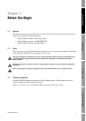
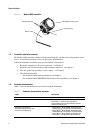
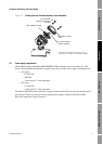
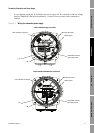
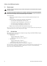
Figure 1-1 Model 2400S transmitter
1.4 Transmitter installation overview
The Model 2400S transmitter component is mounted integrally with the sensor and grounded via the
sensor. To install and ground the sensor, see the sensor documentation.
Additional transmitter installation steps are documented in this manual:
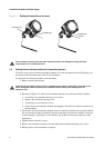
• Rotate the transmitter on the sensor (optional) – see Chapter 2
• Rotate the user interface module on the transmitter (optional) – see Chapter 2
• Wire and ground the transmitter’s power supply – see Chapter 2
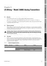
• Wire the transmitter I/O:
- For the Model 2400S Analog transmitter, see Chapter 3
- For the Model 2400S PROFIBUS-DP and DeviceNet transmitters, see Chapter 4
1.5 Flowmeter documentation
Table 1-1 lists documentation sources for other required information.
Table 1-1 Flowmeter documentation resources
Topic Document
Sensor installation Sensor documentation shipped with sensor
Hazardous area installation See the approval documentation shipped with the
transmitter, or download the appropriate
documentation from the Micro Motion web site
(www.micromotion.com)
Transmitter configuration,
flowmeter startup and use, and
flowmeter troubleshooting
• Micro Motion
®
Model 2400S Transmitters with
Analog Outputs: Configuration and Use Manual
• Micro Motion
®
Model 2400S Transmitters with
PROFIBUS-DP: Configuration and Use Manual
• Micro Motion
®
Model 2400S Transmitters with
DeviceNet
™
: Configuration and Use Manual
Transmitter housing cover
Conduit openings
Clamping ring
Sensor case