


16 Micro Motion
®
Model 2400S Transmitters
I/O Wiring – Model 2400S Analog Transmitters
3.4.2 Frequency output wiring
Frequency output wiring depends on whether you will use internal or external power. The following
diagrams are examples of proper wiring for these configurations:
• Internal power – Figure 3-7
• External power – Figure 3-8
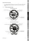
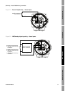
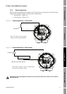
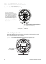
Figure 3-7 Frequency output wiring – Internal power
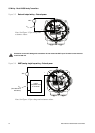
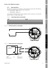
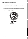
Figure 3-8 Frequency output wiring – External power
Excessive current will damage the transmitter. Do not exceed 30 VDC input. Terminal current must be
less than 500 mA.
Counter
000042
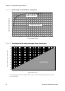
Note: See Figure 3-11 for output
voltage versus load resistance.
+
–
Output voltage level is +24 VDC ±3%
with high resistance load.
–
+
Note: See Figure 3-12 for recommended
resistor versus supply voltage.
000042
Counter
Pull-up resistor
3–30 VDC
+
–