


12 Micro Motion
®
Model 2400S Transmitters
I/O Wiring – Model 2400S Analog Transmitters
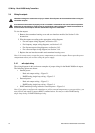
3.4 Wiring the outputs
Hazardous voltage can cause severe injury or death. Shut off power to the transmitter before wiring the
transmitter outputs.
A transmitter that has been improperly wired or installed in a hazardous area could cause an explosion.
Make sure the transmitter is wired to meet or exceed local code requirements. Install the transmitter in
an environment that complies with the classification tag on the transmitter.
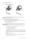
To wire the outputs:
1. Remove the transmitter housing cover and user interface module. See Section 2.4 for
instructions.
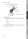
2. Wire the outputs according to the appropriate wiring diagram:
• For mA output wiring diagrams, see Section 3.4.1.
• For frequency output wiring diagrams, see Section 3.4.2.
• For discrete output wiring diagrams, see Section 3.4.3.
• For a discrete input wiring diagram, see Section 3.4.4.
3. Replace the user interface module and transmitter housing cover.
Note: It is not necessary to open the power compartment to wire the outputs. Do not open the power
compartment unless you are also wiring the power supply.
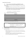
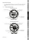
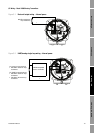
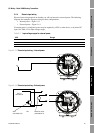
3.4.1 mA output wiring
The wiring diagrams in this section are examples of proper wiring for the Model 2400S mA output.
The following options are shown:
• Internal power:
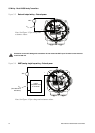
- Basic mA output wiring – Figure 3-1
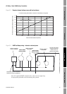
- HART/analog single-loop wiring – Figure 3-2
• External power:
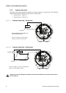
- Basic mA output wiring – Figure 3-3
- HART/analog single-loop wiring – Figure 3-4
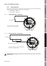
• HART multidrop wiring, internal or external power – Figure 3-6
Note: If you plan to configure the transmitter to poll an external temperature or pressure device, you
must wire the mA output to support HART communications. You may use either HART/analog
single-loop wiring or HART multidrop wiring.