


Installation Manual 11
Power Supply I/O Wiring – DP and DNI/O Wiring – ANBefore You Begin
Chapter 3
I/O Wiring – Model 2400S Analog Transmitters
3.1 Overview
This chapter describes how to wire I/O for Model 2400S Analog transmitters.
Note: To wire I/O for Model 2400S PROFIBUS-DP and DeviceNet transmitters, see Chapter 4.
It is the user’s responsibility to verify that the specific installation meets the local and national safety
requirements and electrical codes.
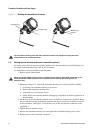
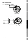
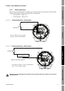
3.2 Moisture protection
When rotating or wiring the transmitter, guard against condensation or excessive moisture inside the
transmitter housing. Be sure that the conduit openings are completely sealed after all installation and
wiring procedures have been performed.
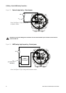
Improperly sealed housings can expose electronics to moisture, which can cause measurement error
or flowmeter failure. Install the meter so that the conduit openings do not point upward, and install drip
legs in conduit or cable. Inspect and grease all gaskets and O-rings. Fully close and tighten all housing
covers and conduit openings.
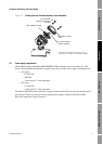
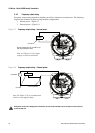
3.3 I/O options
Table 3-1 lists the options for the transmitter’s two I/O channels. Before wiring Channel B, ensure
that you know how it will be configured. For information on configuring Channel B for function and
power, see the manual entitled Micro Motion
®
Model 2400S Transmitters with Analog Outputs:
Configuration and Use Manual.
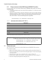
Table 3-1 Terminal configuration options
Channel Terminals Function Power Comm
A 1 & 2 mA Internal
(1)
or external
(1) Factory default.
HART/Bell 202
B 3 & 4 Frequency
(1)
Internal
(1)
or external None
Discrete output Internal or external None
Discrete input Internal or external None