


28 Micro Motion
®
Model 2400S Transmitters
Dimensions and Specifications
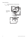
A.4 Electrical connections
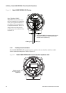
Model 2400S Analog
Input and output connections Two pairs of wiring terminals for transmitter inputs/outputs. Screw terminals accept
solid or stranded conductors, 26 to 14 AWG (0,14 to 2,5 mm
2
).
Power connections One pair of wiring terminals accepts AC or DC power. One internal ground lug for
power supply ground wiring.
Screw terminals accept solid or stranded conductors, 26 to 14 AWG
(0,14to2,5mm
2
).
Digital comm maintenance
connections
Two clips for temporary connection to the service port.
Two clips for temporary connection to HART/Bell 202 terminals.
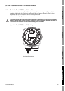
Model 2400S PROFIBUS-DP
PROFIBUS-DP segment One pair of wiring terminals for connection to PROFIBUS-DP segment. Connection
type:
• Screw terminals accept solid or stranded conductors, 26 to 14 AWG
(0,14to2,5mm
2
).
• Five-pin PROFIBUS-DP M12 (Eurofast) female connector (optional).
Power connections One pair of wiring terminals accepts AC or DC power. One internal ground lug for
power supply ground wiring.
Screw terminals accept solid or stranded conductors, 26 to 14 AWG
(0,14to2,5mm
2
).
Digital comm maintenance
connections
Two clips for temporary connection to the service port.
Model 2400S DeviceNet
DeviceNet segment One pre-installed male 5-pin Eurofast connector for I/O and power supply wiring
Digital comm maintenance
connections
Two clips for temporary connection to the service port.