


Installation Manual 35
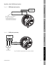
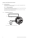
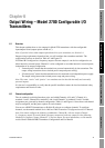
Output Wiring – Model 1700/2700 Intrinsically Safe Transmitters
Output Wiring – Configurable I/O SpecificationsOutput Wiring – Fieldbus/PROFIBUSOutput Wiring – Intrinsically Safe
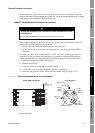
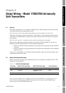
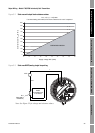
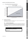
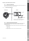
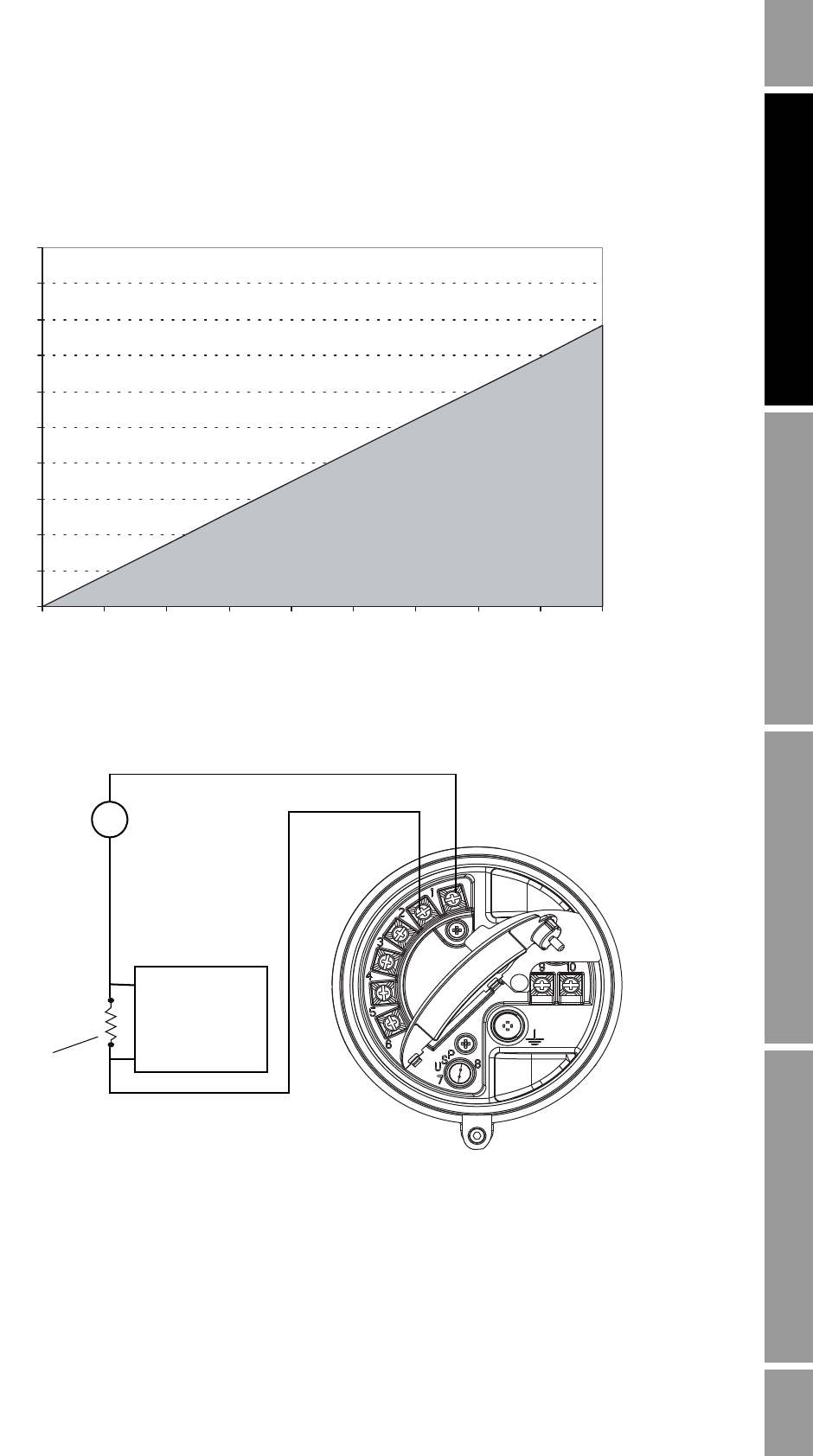
Figure 5-2 Safe area mA output load resistance values
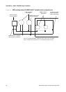
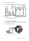
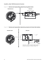
Figure 5-3 Safe area HART/analog single-loop wiring
0
100
200
300
400
500
600
700
800
900
1000
12 14 16 18 20 22 24 26 28 30
R
max
= (V
supply
– 12)/0.023
If communicating with HART, a minimum of 250 Ω and 17.5 V is required
Supply voltage VDC (Volts)
External resistor R
load
(Ohms)
OPERATING REGION
Note: See Figure 5-2 for voltage and resistance values.
VDC
R
load
(250–600 Ω
resistance)
+
–
+
–
HART-
compatible host
or controller
mA1