


Installation Manual 29
Installing the Transmitter Output Wiring – AnalogSensor WiringBefore You Begin
Chapter 4
Output Wiring – Model 1700/2700
Analog Transmitters
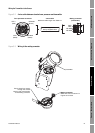
4.1 Overview
This chapter explains how to wire outputs for Model 1700 or 2700 transmitters with the analog
outputs option board (output option code A).
Note: If you do not know what outputs option board is in your transmitter, see Section 1.4.
It is the user’s responsibility to verify that the specific installation meets the local and national safety
requirements and electrical codes.
4.2 Output terminals and output types
Table 4-1 describes the outputs and communication protocols available for the Model 1700 or 2700
analog transmitter.
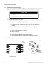
4.3 Output wiring
Output wiring requirements depend on how you will use the analog functionality and the HART or
Modbus protocol. This chapter describes several possible configurations:
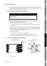
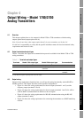
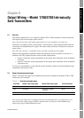
• Figure 4-1 shows the wiring requirements for the mA output (terminals 1 and 2) and the
frequency output (terminals 3 and 4).
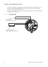
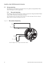
• Figure 4-2 shows the wiring requirements for the mA output (terminals 1 and 2) if it will be
used for HART communications in addition to the mA signal.
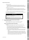
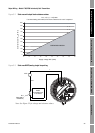
• Figure 4-3 shows the wiring requirements for RS-485 communications using the RS-485
output (terminals 5 and 6).
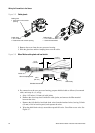
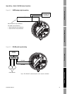
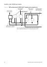
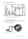
• Figure 4-4 shows the wiring requirements for connecting the transmitter to a HART multidrop
network.
Table 4-1 Terminals and output types
Terminals Model 1700 output type Model 2700 output type Communication
1 & 2 Milliamp/Bell 202
(1)
(1) The Bell 202 signal is superimposed on the mA output.
Milliamp/Bell 202
(1)
HART
3 & 4 Frequency • Frequency (default)
• Discrete
None
5 & 6 RS-485 RS-485 • HART (default)
• Modbus