


Installation Manual 21
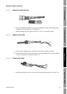
Wiring the Transmitter to the Sensor
Installing the Transmitter Output Wiring – AnalogSensor WiringBefore You Begin
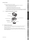
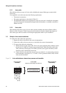
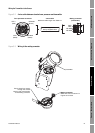
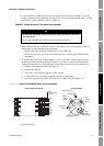
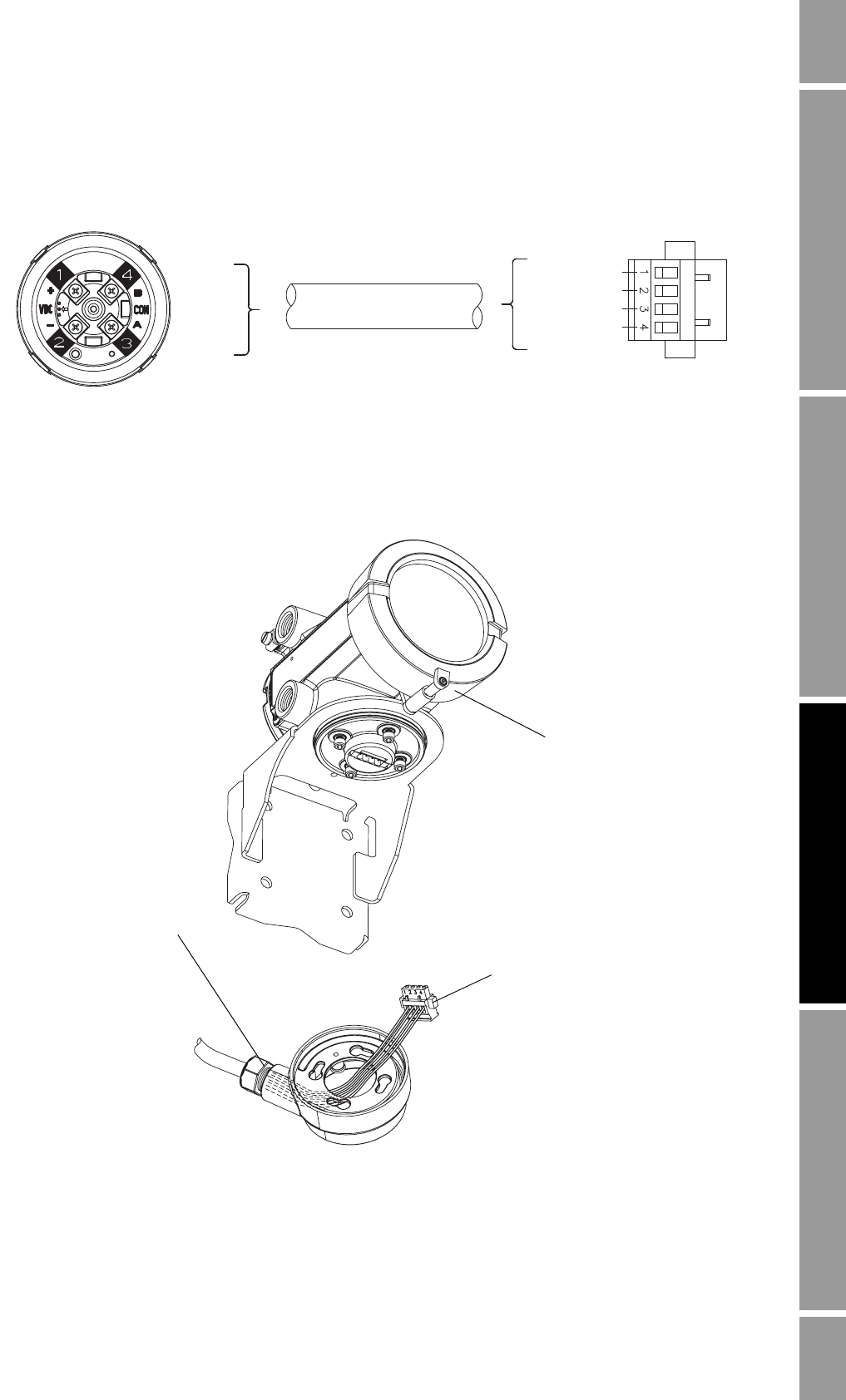
Figure 3-2 4-wire cable between standard core processor and transmitter
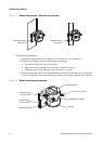
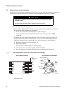
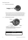
Figure 3-3 Wiring to the mating connector
Core processor terminals 4-wire cable Mating connector
(transmitter)
Maximum cable length: see Table 2-2
VDC+
(Red)
VDC–
(Black)
RS-485B
(Green)
RS-485A
(White)
VDC+
VDC–
RS-485A
RS-485B
User-supplied or
factory-supplied cable
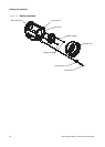
Mating connector
Match wire colors as shown in
Figures 3-1 and 3-2
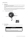
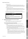
Transmitter
Feed 4 wires from sensor
through the conduit
opening and connect them
to the mating connector