


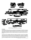
ELECTRO-VOICE
®
X-Line Very Compact
TM
Rigging Manual 6
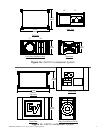
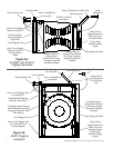
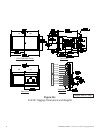
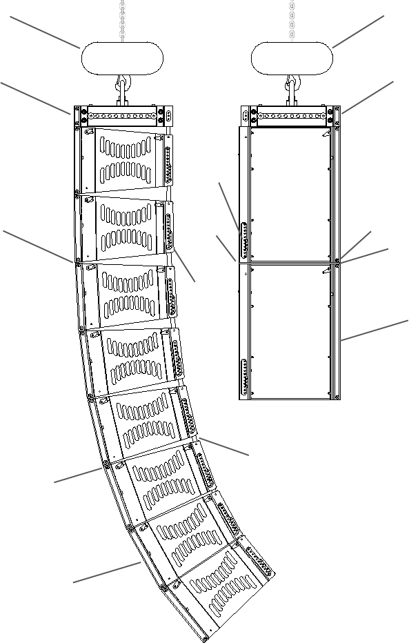
Figure 2:
Typical XLVC Flying System
(without Coupler Beam)
Hoist Motor
XLD281 Enclosures
Grid
Eight XLD281
Enclosures Hinged at the
Front by the Extended
Hinge Bars and Front
Rigging Tube Modules
Angles Between
Enclosures fixed by Pins
through the Swing Arms
and Rear Rigging Holes
in the Channel Modules
Swing Arm
Hinge Bar
XS212 Enclosures
Two XS212 Enclosures
Hinged at the Front by
the Extended Hinge Bars
and Rigging Tube
Modules
Hinge Bar
Swing
Arm
Hoist Motor
Grid
Quick-Release Pin
Quick-
Release
Pin
Quick-
Release
Pin
Quick-
Release Pin
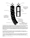
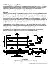
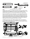
The swing arm from an enclosure below can be pivoted up so that the quick-release pin from the
enclosure below may be inserted through a hole in the rigging slot on the channel module above,
linking the two enclosures together. The vertical tilt angle of the bottom enclosure is then
determined by the hole in which the swing arm is pinned. This pin fixes the maximum distance the
back corners of the enclosures may be separated. The XLD281 and XLE181 enclosures may be
angled from 0° to 10° in 1° increments, while the XS212 enclosure may be angled from 0° to 20°
in 2° increments.
The XLD281 and XS212 loudspeaker systems may be rigged together in the same column
because they have the same width. However, the XLE181 system may not be rigged to either an
XLD281 or XS212 because it is not as wide.
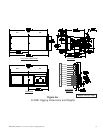
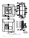
The center of gravity and rigging dimensions for all of the XLVC loudspeaker systems are shown
in Figure 4. This figure includes sufficient information to calculate the vertical angle of XLVC
enclosures that are rigged together in a column, as well as the weight distribution throughout the
column.