


ELECTRO-VOICE
®
X-Line Very Compact
TM
Rigging Manual
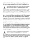
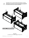
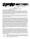
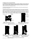
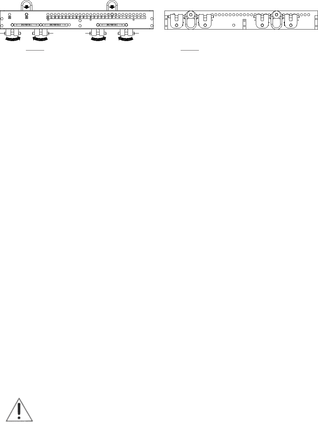
Figure 9e:
CBEAM Shipping/Transport Configuration
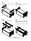
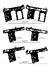
Step 1: Install Pickup Rings in Hole #10
and #29 and Yokes in Positions A and C
Step 2: Rotate Yokes, Then Drop Pickup Rings
(View Shown Cutaway for Clarity)
2.5 Using the XLVC-BGK and Grid for Pull Up
The XLVC-BGK is a rigging kit with the hardware necessary to install front hinge bars and rear
swing arms on the bottom of the XLD281 and XLE181 loudspeaker system enclosures. This
makes it possible to attach a grid to the bottom of an enclosure. The bottom grid can be used as a
pull back on the bottom of a column to achieve downward tilt angles for the entire array that are
greater than could be achieved from just a grid.
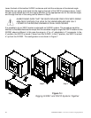
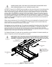
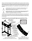
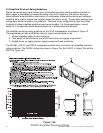
The XLVC-BGK consists of two front hinge bars, two rear swing arms, a shoulder bolt for the
hinge bars and four sets of quick-release pins with screws to attach the lanyards to the enclosure
rigging, as shown in Figure 10a.
Install the rectangular ends of the two hinge bars into the front rigging tubes the XLVC enclosure,
as shown in Figure 10a, and secure each in the tubes with a quick-release pin having a green
lanyard. The front hinge bars are mirror image. Make sure that the hinge bars are installed into the
rigging tubes on the enclosure so that the two holes on the back side of the tube line up with the
two holes on the bars. If the holes do not line up, exchange the left and right bars. Install the large
hex-socket-head shoulder bolt through the slot in the rigging tube into the rear of the front hinge
bars. The head of this bolt will serve as a handle to move the hinge bars in and out of the tubes.
On each side of the enclosure, insert one of the small hex-socket-head bolts through the tab of
the lanyard securing the hinge bar and through the tab of another matching quick-release pin
having a green lanyard, then screw the bolt into the threaded hole on the side of the enclosure
rigging. The extra quick-release pin on each side will be used to secure the hinge bars to the
bottom grid. The newly added rigging should match the hinge bar and lanyards at the top of the
enclosure. The extra front hinge bars at the bottom can be retracted into the rigging tubes during
transport.
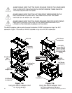
Secure the swing arms to rigging channels on each side of the enclosure by inserting a quick-
release pin having a yellow lanyard into the 3° hole on the rigging channel, as shown in Figure
10a. The extra quick-release pins having a yellow lanyard will be used to attach the loose end of
the swing arms to the bottom grid. There is insufficient room for both sets of swing arms to be
retracted into the rear rigging channel during transport. Therefore, the bottom set of swing arms
and quick-release pins will need to be removed when the enclosure is transported. Because the
extra hardware must be removed, screws are not provided to attach the rear lanyards to the sides
of the enclosure rigging.
ALWAYS MAKE SURE THAT THE QUICK-RELEASE PINS ON THE HINGE BARS
FULLY LOCK INTO THE ROUND HOLES IN THE FRONT RIGGING TUBES ON
BOTH THE ENCLOSURE AND THE GRID.
30