


ELECTRO-VOICE
®
X-Line Very Compact
TM
Rigging Manual
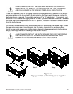
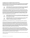
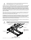
2.3 Rigging the XLVC Loudspeaker Systems and XLVC Grids
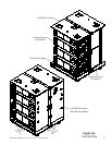
Attach the top enclosure in the array to the grid, as shown in Figure 8a. (Only an XLVC compatible
grid can be used with an XLVC array.) The grid has front rigging tubes similar to the enclosures.
Slide the front hinge bar of the top enclosure into the front tube of the grid using the same tech-
nique that was used to link two enclosures.
ALWAYS MAKE SURE THAT THE QUICK-RELEASE PINS ON THE HINGE BARS
FULLY LOCK INTO THE ROUND HOLES IN THE FRONT RIGGING TUBES ON
BOTH THE ENCLOSURE AND THE BOTTOM HOLE OF THE GRID.
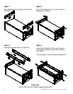
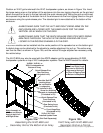
The grid also has a rear rigging channel similar to the enclosures, except that the grid only has
three attachment holes available. Unlock the rear swing arm from the top enclosure by removing
the quick-release pin from the rear rigging channel on the enclosure. Pivot the rear swing arm on
the enclosure up into the rear rigging channel on the grid. Insert the quick-release pin from the
grid through one of the three holes in the rear rigging channel on the grid (top hole is 0°, middle
hole is 2° up, and bottom hole is 4° up) and through the hole in the swing arm. Repeat the pro-
cess for the other side of the enclosure and grid.
ALWAYS MAKE SURE THAT THE LEFT AND RIGHT SWING ARMS ON THE
ENCLOSURE ARE LOCKED INTO THE SAME HOLES FOR THE SAME VERTICAL
SPLAY ANGLE ON THE GRID.
ALWAYS MAKE SURE THAT THE QUICK-RELEASE PINS FOR EVERY SWING
ARM PASS THROUGH THE HOLE IN THE SWING ARM AND ARE FULLY
LOCKED IN THE RIGGING CHANNELS IN THE GRID.
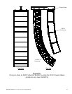
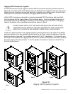
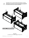
The grid sidearms are the attached to either one or two spreader bars as shown in Figure 8a.
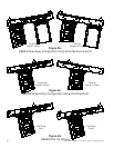
When two spreader bars are used, one is attached to the sidearms at the (one at the front and
one at the rear), the spreader bars are attached to the front and rear of the sidearms and two
hoist motors are used to lift the array, as shown in Figure 8b. In this case, the hoist motors are
used to adjust the vertical angle of the entire column of loudspeakers. When one spreader bar is
used, the vertical angle of the entire column of loudspeakers is determined by the front-to-back
position at which the spreader bar is attached to the sidearms. There are a series of holes in the
sidearms the user may select to adjust the vertical array angle.
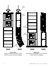
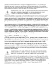
When one spreader bar is used, the vertical angle of the entire column of loudspeakers is
determined by the front-to-back position at which the spreader bar is attached to the sidearms.
There are a series of holes in the sidearms the user may select to adjust the vertical array angle.
The grid with a single spreader bar may be picked up using one hoist motor attached to the center
hole in the spreader bar, or may be picked up using two hoist motors side-to-side using the two
holes at the ends of the spreader bar, as shown in Figure 8b.
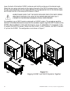
Large quick-release pins that are tethered to the spreader bars are used to secure the side arms
to the spreader bars.
24