


ELECTRO-VOICE
®
X-Line Very Compact
TM
Rigging Manual27
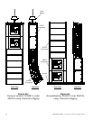
2.4 Rigging the XLVC Grids and the CBEAM
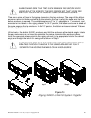
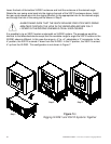
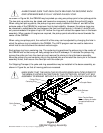
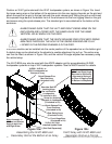
The CBEAM, shown in Figure 9a, may be used as either a coupler beam for a dual array to hang
a column subwoofer systems behind a column of full-range systems, or may be used as an
extender beam to hang a single array of full-range systems where more vertical tilt angle is
required than could be achieved from only a grid.
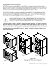
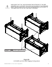
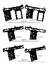
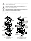
The CBEAM is shown in use as a coupler beam for a dual-array configuration in Figure 9b. Each
column of loudspeakers is suspended by an XLVC grid and the two grids are in turn secured to
the CBEAM at Grid Position A and Grid Position C. Note that the orientation of the CBEAM will
change depending on whether the entire array needs to tilt up or down. If the entire array needs to
be tilted down, Hole #1 in the CBEAM must be pointed away from the audience (upstage) and the
column of full-range systems (either XLD281 or XLE181) are attached at Grid Position A and the
XS212 subwoofers are attached at Grid Position C. If the entire array needs to be tilted up, Hole
#1 in the CBEAM must be pointed towards the audience (downstage) and the column of XS212
subwoofers are attached at Grid Position A and the full-range systems (either XLD281 or XLE181)
are attached at Grid Position C.
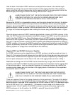
The CBEAM is shown in use as an extender beam for a single-array configuration in Figure 9c. In
this case, the column of full-range systems (either XLD281 or XLE181) are always attached at
Grid Position B. However, the CBEAM orientation will change depending which way the array
needs to be tilted. If the entire array needs to be tilted down, Hole #1 in the CBEAM must be
pointed away from the audience (upstage). If the entire array needs to be tilted up, Hole #1 in the
CBEAM must be pointed away from the audience (upstage). Because the CBEAM extends
beyond the end of the grid, greater tilt angles for the array (either up or down) can be achieved
than would be possible with just a grid alone. In fact, for most applications, the CBEAM eliminates
the need for a pull back for severe downward angles.
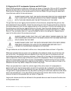
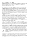
The XLVC grids (either XLD Grid or XLE Grid) must always be attached to the CBEAM using two
spreader bars on each grid, as shown in Figure 9a. One spreader bar must be attached to the grid
side arms at the last hole at the front and the other at the last hole at the rear. The grid spreader
bars are then secured to the CBEAM yoke assemblies.
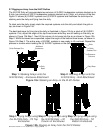
First select the position on the CBEAM for the grid attachment (Grid Position A, B or C) and install
the CBEAM yoke assemblies in those positions. The yoke assemblies are secured to the beam
assembly by large clevis pins. To relocate a yoke assembly, remove the cotter pin from the clevis
pin and remove the clevis pin from the beam assembly. Move the yoke to the desired hole and
reinstall the clevis pin in the beam assembly holes, then secure the clevis pin with the cotter pin.
ALWAYS MAKE SURE THAT THE EACH CLEVIS PIN SECURING EACH YOKE
ASSEMBLY TO THE BEAM IS LOCKED IN POSITION BY THE COTTER PIN. DO
NOT LIFT ANY ASSEMBLY OVERHEAD WITHOUT A COTTER PIN TO LOCK
EACH CLEVIS PIN.
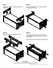
To attach a grid to the CBEAM, remove the quick-release pins from the two yoke assemblies that
will support the grid. Position the grid underneath the CBEAM and slide the two yokes over the
two spreader bars. Insert the quick-release pins through each yoke and spreader bar. To make
sure that the quick-release pins are fully locked into the yoke, always push the pins in all the way
in so that spring-loaded balls are visible at the opposite side of the yoke.